
Thin layer chromatography quantitative analysis method based on image processing technology

A technology of image processing and quantitative analysis, which is applied in the direction of analyzing materials, measuring devices, and material separation, etc., and can solve problems such as poor application of camera imaging methods, poor repeatability, and uncertain aperture

Inactive Publication Date: 2006-05-03
TSINGHUA UNIV
View PDF0 Cites 14 Cited by
  • Summary
  • Abstract
  • Description
  • Claims
  • Application Information

AI Technical Summary

Problems solved by technology

However, after using a video camera for thin-layer chromatography analysis, the conclusions drawn are not very good
The reason is that compared with traditional thin-layer scanners, the accuracy of camera imaging is restricted by the uniformity of illumination, so the results are not very accurate and the repeatability is not good
In addition to the reasons they pointed out, when the camera is imaging, the light source, the aperture, and the exposure speed are not fixed, which also brings difficulties to the research, that is, the repeatability is not strong.
It is these problems that prevent the camera imaging method from being well applied in quantitative analysis in thin layer chromatography

Method used


Image

  • Thin layer chromatography quantitative analysis method based on image processing technology
  • Thin layer chromatography quantitative analysis method based on image processing technology
  • Thin layer chromatography quantitative analysis method based on image processing technology

Examples


Embodiment Construction

[0038] Fig. 1 has provided the hardware composition block diagram of the present invention. The thin-layer plate 1 carrying the sample is placed in the light box 2, and then it is photographed by a video camera or a digital camera 3, and the formed image is sent to a computer or a DSP processing system 4, and the processed result is sent to a printer 6 for printing or Standby in other equipment 7. The monitor 5 in FIG. 1 is used to display the captured images and the running process of the program.

[0039] Fig. 2 has provided the workflow block diagram of the present invention, comprises taking thin-layer plate image (the first step); Image preprocessing (the second step) such as lens distortion correction, noise filtering is done to photographed image; Utilize image longitudinal pixel The gray integral projection determines the abscissa of the control point, and then obtains the ordinate of the control point by using the distance equalization to obtain the control point (th...


PUM


Abstract

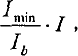
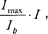
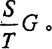
The invention belongs to digital image processing and chemical analyzing domain, which is characterized in that it uses digital camera or video camera to sight the lathe on the light condition with different wavelength; it dose lens distortion correction and noise reduction process to the image; it uses the character of point sampling time point equidistribution and the rule of vertical distance five equilibrium to ascertain the control point; it uses bracketing method to construct image background by the control point; it exorcizes the background image from the adjusted thin layer image and dose brightness normalization to each image element point of the constructed background image; it divides the thin layer image and dose monomer to the grey of each area by the dividing result.

Description

Technical field [0001] The invention belongs to the field of computer digital image processing and chemical analysis. Background technique [0002] In the fields of chemical analysis, biomedicine, pharmaceutical research, clinical medicine, food processing and other fields, the detection and identification of certain trace material components is a very necessary task. Among them, thin layer chromatography or thin layer chromatography (Thin Layer Chromatography) LayerChromatography (TLC for short) is widely used. The so-called thin layer chromatography is a method of spreading an adsorbent (such as silica gel or alumina) onto a flat object such as a glass plate, plastic sheet or metal foil to form a thin layer, and then using a solvent to develop and separate the sample. It is a method A simple, economical, micro-volume, and widely applicable chromatographic method. Thin layer chromatography mainly consists of three steps: spotting of the sample, unfolding the sample after ...

Claims


Application Information

Patent Timeline
IPC IPC(8): G01N30/90G06K9/34G06K9/54
CPCG01N30/95
Inventor 张利
Owner TSINGHUA UNIV
Learn More