Thread cutting insert

A thread cutting and blade technology, applied in cutting blades, thread cutting tools, tools for lathes, etc., can solve the problems of high-frequency vibration, increased cutting resistance, and reduced surface precision of finishing, and achieve the purpose of suppressing the increase of resistance big effect

Active Publication Date: 2006-05-03
MITSUBISHI MATERIALS CORP
View PDF4 Cites 8 Cited by
  • Summary
  • Abstract
  • Description
  • Claims
  • Application Information

AI Technical Summary

Problems solved by technology

However, since this inclined surface is a primary inclined surface rising from the front to the boss surface, it is necessary to set the height at which it protrudes from the front so that the chips generated in the second half cycle can reliably collide with the inclined surface and be curled. In this case, the chip is rounded and curled at once and its flow direction is changed sharply, so the cutting resistance increases and high-frequency vibrations are generated on the workpiece or the tool body, which may reduce the accuracy of the finished surface

Method used


Image

  • Thread cutting insert
  • Thread cutting insert
  • Thread cutting insert

Examples


Embodiment Construction

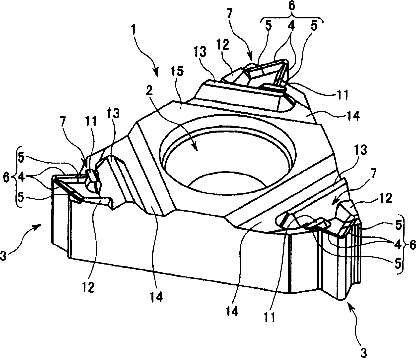
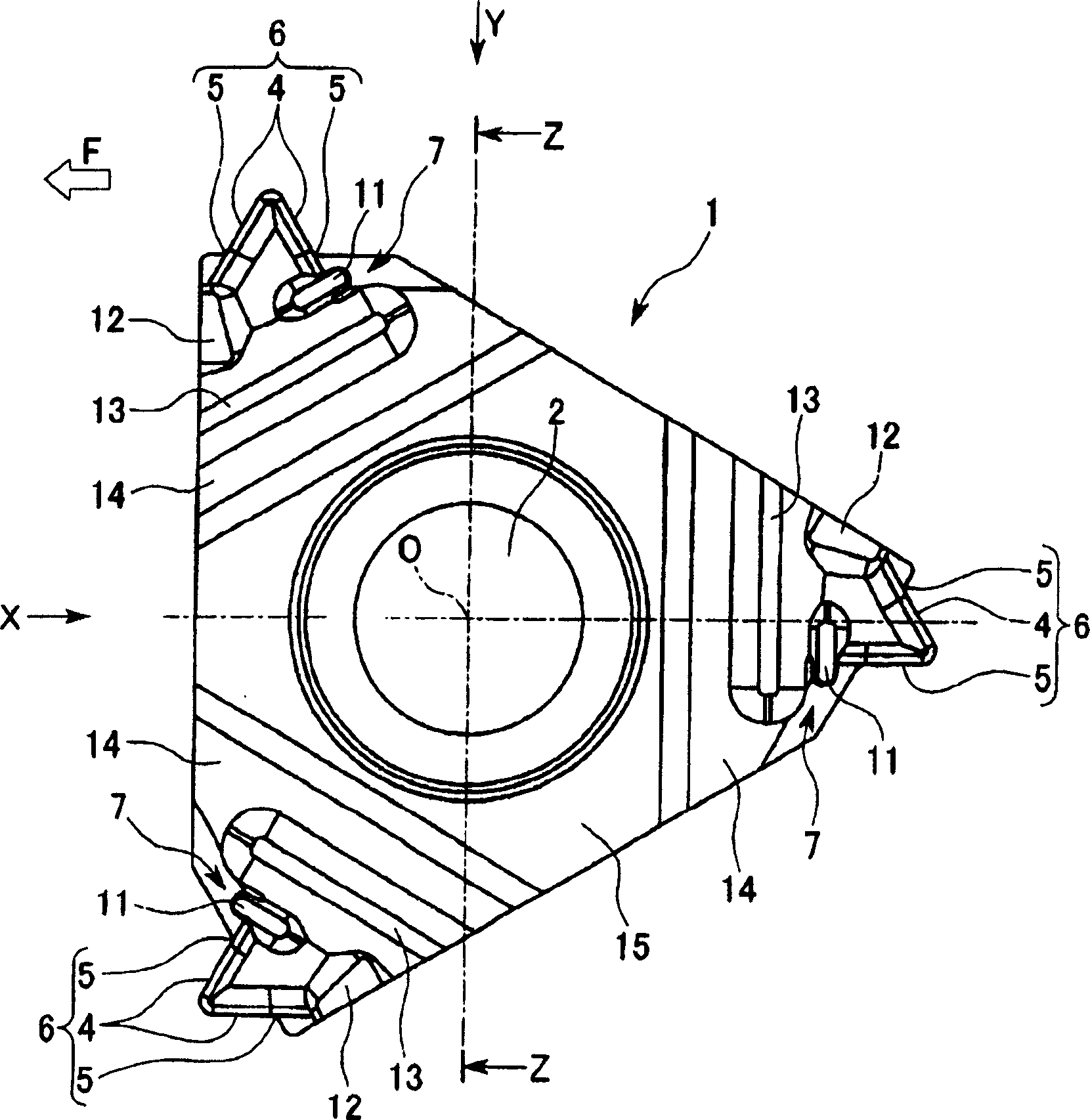
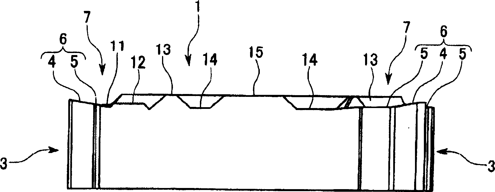
[0036] Figure 1 to Figure 14 An embodiment of the present invention is shown. In this embodiment, the insert body 1 is made of a hard material such as cemented carbide, such as figure 2 As shown in the flat shape forming a roughly equilateral triangle, in the center of the upper and lower surfaces constituting a roughly equilateral triangle, there are openings along the thickness direction ( figure 1 , 3 Up and down directions in ~5. Hereinafter referred to as the blade thickness direction) through the circular mounting hole 2 of the blade main body 1 , the blade main body 1 is a 120° rotationally symmetrical shape about the center line O of the mounting hole 2 . Also, in a plan view along the center line O, the corners of the above-mentioned equilateral triangle formed by the blade body 1 are as follows: figure 2 As shown, a cut is made in a manner substantially perpendicular to one of the edge parts intersecting at the corner, and at the part of the cut, as Image 6 ...


PUM


Abstract

A thread cutting insert includes main cutting edges that have a pair of thread cutting edges and wiper thread cutting edges for full profile on side edges of a rake face formed on the insert body respectively. / The pair of thread cutting edges is formed in a convex V shape as viewed in a plane facing the rake face, and the wiper thread cutting edges for full profile are connected to posterior ends of the thread cutting edges, / An inner portion of a V-shaped projection of the rake face, which is formed on the front side of the wiper thread cutting edge for full profile by the pair of thread cutting edges, is formed not to protrude from the thread cutting edges as viewed in the plane, / A first convex protrusion projecting from the rake face, a second convex protrusion higher than the first convex protrusion, and the third convex protrusion higher than the first and second convex protrusions project on the rear side of the wiper thread cutting edge for full profile of the rake face as viewed in the plane, and the first and second convex protrusions are positioned closer to the main cutting edge than the third convex protrusions.

Description

technical field [0001] The present invention relates to an insert for thread cutting which is held on a tool body of an insert-detachable cutting tool for thread cutting a workpiece. Background technique [0002] As such an insert for thread cutting, for example, in Patent Documents 1 to 4, it has been proposed that a front surface is formed at each corner of a triangular surface constituting a triangular flat plate-shaped insert body, and that a front surface is formed at each corner of a triangular plate-shaped insert body, and that a front surface is formed on an edge portion of the front surface. A pair of thread cutting edges are formed, and the pair of thread cutting edges form a convex V-shape corresponding to the cross-sectional shape of the thread to be cut in a plan view facing the front face. [0003] Such thread cutting inserts are generally used to perform thread cutting on the peripheral surface of a workpiece that is rotated by a plurality of cycles of turning...

Claims


Application Information

Patent Timeline
Patent Type & Authority Applications(China)
IPC IPC(8): B23G5/00
CPCB23B27/065B23B2200/321Y10T407/24Y10T407/235Y10T407/245Y10T407/23B23C5/00B23B27/16B23C5/20
Inventor 名田丰一关修
Owner MITSUBISHI MATERIALS CORP
Why Eureka
Try Eureka