Battery can and manufacturing method thereof and battery using the same

A battery shell and electrolyte technology, applied to small-sized batteries/battery packs, dry batteries, secondary batteries, etc., can solve the problems of increased internal resistance of batteries, increased contact resistance, and insufficient corrosion resistance of battery shells, etc., to achieve low cost effect

Inactive Publication Date: 2006-04-05
PANASONIC CORP +1
View PDF0 Cites 4 Cited by
  • Summary
  • Abstract
  • Description
  • Claims
  • Application Information

AI Technical Summary

Problems solved by technology

From these points of view, the corrosion resistance of conventional battery cases is not enough
[0010] In addition, primary batteries have an additional problem that the use of ultra-low carbon steel sheets in order to reduce the cost of their battery cases leads to an increase in the internal resistance of the batteries
This problem is caused by the insufficient strength of the battery case due to the use of an ultra-low carbon steel sheet having a carbon content of less than 0.009% by weight, thereby resulting in an increase in the contact resistance between the positive electrode material mixture and the inner surface of the battery case

Method used


Image

  • Battery can and manufacturing method thereof and battery using the same
  • Battery can and manufacturing method thereof and battery using the same
  • Battery can and manufacturing method thereof and battery using the same

Examples


example 1

[0060] (i) Ni plating treatment

[0061] Ring-shaped cold-rolled steel sheets (No. 1 to 19) having a thickness of 0.4 mm were prepared as battery case materials. These steel sheets contained components as listed in Table 1 in addition to Fe and impurities as main components. Each steel plate was plated with Ni on both sides thereof. The conditions of Ni plating are shown in Table 2.

[0062]

Steel plate number

Steel composition (% by weight)

C

mn

P

Si

Al

S

1

0.001

0.020

0.010

0.020

0.040

0.010

2

0.002

0.020

0.010

0.020

0.040

0.010

3

0.004

0.020

0.010

0.020

0.040

0.010

4

0.005

0.020

0.010

0.020

0.040

0.010

5

0.008

0.020

0.010

0.020

0.040

0.010

6

0.020

0.020

0.010

...

example 2

[0100] Next, the effect of bright Ni plating will be described.

[0101] Using a steel sheet having the same composition as the steel sheet numbered 2 in Table 1, battery cases and batteries were fabricated in the same manner as in Example 1, except that bright Ni plating was not applied or by changing the thickness of the bright Ni layer. Cycle life tests were performed on these batteries. The results are shown in Table 6. The thickness of the bright Ni layer shown in Table 6 is its thickness on the bottom inner surface of the battery case. As is clear from Table 6, a bright Ni layer having a thickness of 0.5 µm or more gave good results.

[0102] Steel plate number

[0103] When a bright Ni layer exists in a corrosive environment, the uppermost bright Ni layer serves as an anode, and corrosion spreads in the lateral direction (direction perpendicular to the thickness direction of the bright Ni layer). However, since the Ni layer under the bright Ni layer serves ...

example 3

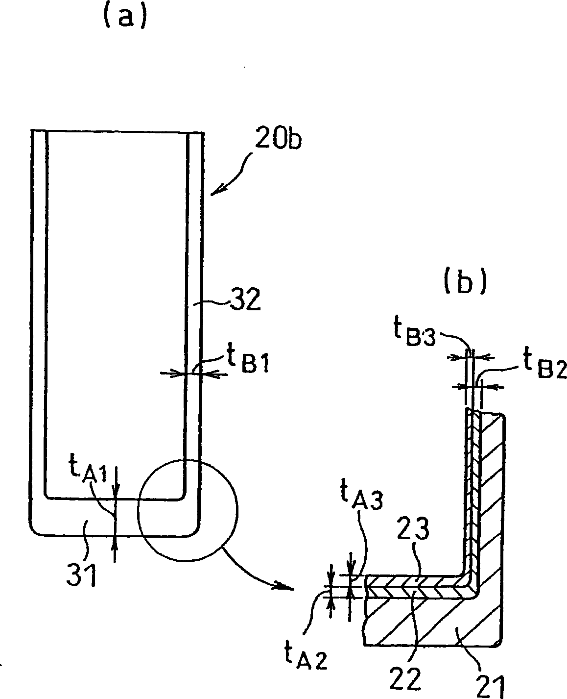
[0105] Next, explain t A1 / t B1 , t A2 / t B2 , and t A4 / t B4 value.

[0106] Use a steel plate with the same composition as the steel plate numbered 2 in Table 1, except by changing t A1 / t B1 , t A2 / t B2 , and t A4 / t B4 Except for the corresponding values ​​of , a battery case and a battery were prepared in the same manner as in Example 1. Cycle life tests were performed on these batteries. The results are shown in Table 7. In order to achieve the t listed in Table 7 A1 / t B1 , t A2 / t B2 , and t A4 / t B4 The value of , changing the size and number of each mold and the size of the punching machine in the battery case forming process (ie, DI process).

[0107]

Steel plate number

battery case

Lithium-ion secondary battery

nickel metal hydride storage

Battery

t A1 / t B1

t A2 / t B2

t A4 / t B4

Numbering

cycle life

Numbering

cycle life

2

2

2

2

2 ...


PUM

PropertyMeasurementUnit
thicknessaaaaaaaaaa
thicknessaaaaaaaaaa
thicknessaaaaaaaaaa

Abstract

A battery can having an opening, comprising a cylindrical side wall and a bottom, wherein said battery can is formed from a steel plate, and said steel plate has a carbon content of 0.004% by weight or less, and wherein a matte or semi-bright nickel layer of 0.5 to 3 µm in thickness is formed on an inner face of the battery can, with a nickel-iron alloy layer of 0.5 to 3 µm in thickness interposed between the matte or semi-bright nickel layer and the inner face of the battery can, and a bright nickel layer of 0.5 to 3 µm in thickness is further formed on the matte or semi-bright nickel layer.

Description

technical field [0001] The present invention relates to a high-quality battery case used as a case for alkaline dry batteries, alkaline secondary batteries, and nonaqueous electrolyte secondary batteries including lithium ion batteries, and to a battery capable of producing such batteries with high yield and low cost shell method. The invention also relates to a battery comprising such a high-quality battery casing. Background technique [0002] With the growth of portable devices in recent years, the number of batteries used therein has been increasing, thereby leading to a strong demand in the market to reduce the prices of primary and secondary batteries. [0003] Under such circumstances, a DI (Drawing and Ironing) process has been suggested as a method for manufacturing battery cases in order to increase the yield of battery cases and reduce their prices (see, for example, Japanese Laid-Open Patent Publication No. Hei 8- 55613). According to the DI process, a steel p...

Claims


Application Information

Patent Timeline
Patent Type & Authority Applications(China)
IPC IPC(8): H01M2/02C25D5/26C22C38/00H01M6/08H01M10/05H01M10/052H01M10/0566H01M10/30H01M50/119H01M50/128H01M50/133
CPCY02E60/124Y02E60/122H01M2/0217H01M2/022H01M2/023Y02E60/12H01M2002/0297B32B15/013H01M2/0287B32B15/015H01M2/0275Y10T428/12958Y10T428/12951Y02E60/10H01M50/56H01M50/103H01M50/107H01M50/131H01M50/124H01M50/133H01M50/119H01M50/128
Inventor 森克彦北川幸平松尾明友森龙夫本田义孝山根荣治
Owner PANASONIC CORP
Why Eureka
Try Eureka