Dewater device of water-jet loom

A dehydration device, water spray technology, applied in the direction of looms, weaving auxiliary equipment, textiles, etc., can solve the problem of not being able to obtain the suction force of the suction device, and achieve the effect of uniform moisture content

Inactive Publication Date: 2006-01-25
TSUDAKOMA KOGYO KK
View PDF1 Cites 6 Cited by
  • Summary
  • Abstract
  • Description
  • Claims
  • Application Information

AI Technical Summary

Problems solved by technology

[0008] However, since the piping extends from the reverse yarn supply side to the air-water separator installed on the yarn supply side, sufficient suction force of the suction device cannot be obtained on the reverse yarn supply side.

Method used


Image

  • Dewater device of water-jet loom
  • Dewater device of water-jet loom
  • Dewater device of water-jet loom

Examples


Embodiment Construction

[0017] Hereinafter, embodiments of the present invention will be described in detail with reference to the accompanying drawings,

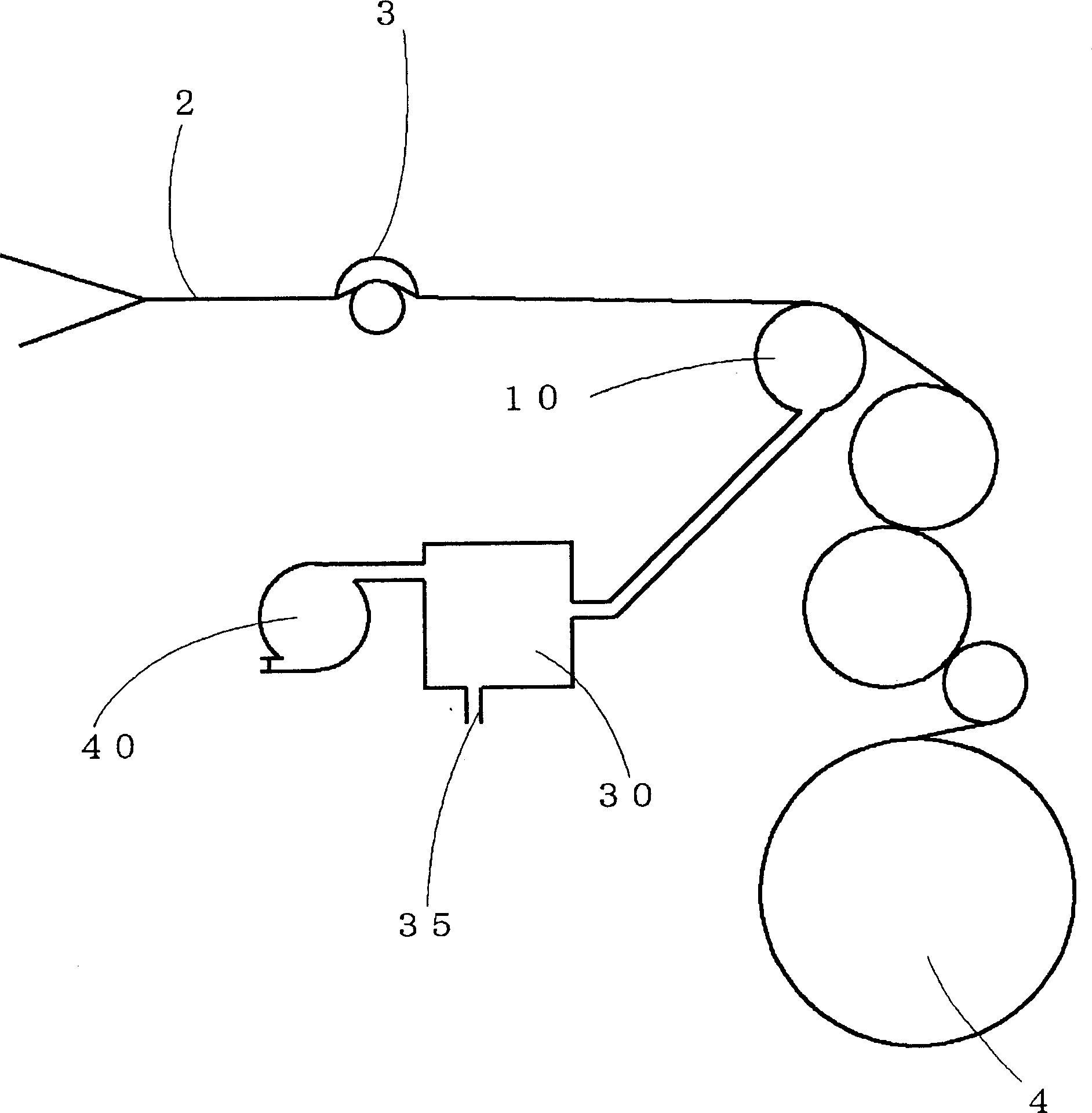
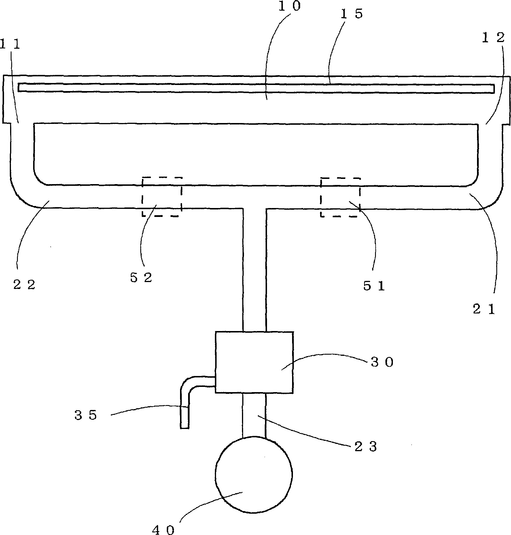
[0018] The first example is figure 1 and figure 2 shown. The fabric 2 passes through a tenter 3 and through a suction duct 10 , travels between rollers and is wound on a winding shaft 4 . On the fabric contact surface of the suction pipe 10, a suction port 15 is provided along the width direction of the fabric 2, and moisture contained in the fabric is sucked from the suction port 15. The suction port 15 may be a slit or a member provided with a plurality of holes. The gas-water separator 30 and the suction device 40 are connected to the suction pipe 10 through piping.

[0019] The suction pipe 10 is provided across the entire area in the web direction. On the suction port 12 of the anti-weft insertion side of the suction pipe 10, a first connection pipe 21 is provided, and a second connection pipe 22 is provided on the suction port 11 of th...


PUM


Abstract

The invention provides a machine dehydration plant of the water spray weaving machine, consisting of a pumping pipe, a moisture trap, an aspirator, a first connecting pipe, a second connecting pipe, a third connecting pipe, wherein the pumping pipe is arranged between the frame of the loom and is provided with an attracting opening which contacts the fabric; the first connecting pipe is connected with the common moisture trap from the anti-yarn feeding lateral terminal part of the pumping pipe; the second connecting pipe is connected with the moisture trap from the yarn feeding lateral terminal part of the pumping pipe; the third connecting pipe connects the moisture trap and the aspirator; the pressure loss of the first connecting pipe is equal to or less than the pressure loss of the second connecting pipe. The machine dehydration plant of the water spray weaving machine is capable of keeping the water ratio of dehydrated fabric more evenly.

Description

technical field [0001] The invention relates to an on-machine dehydration device of a water jet loom. Background technique [0002] On water-jet looms, after weaving, moisture is sucked from the fabric containing water for dehydration. On the suction pipe extending across the web, there is provided a suction port across the web on the contact surface with the fabric. The water sucked out from the suction port is sucked from the pipe provided at one end of the suction pipe and discharged into the air-water separator. There is a suction device in front of the gas-water separator. [0003] Patent Document 1 discloses an on-machine dehydration device for a water jet loom that improves such a dehydration device. [0004] Patent Document 1 is an on-machine dehydration device of a water jet loom in which a pipe extending from a conventional air-water separator to a suction pipe is branched and connected to both ends of the suction pipe. [0005] [Patent Document 1] Japanese Une...

Claims


Application Information

Patent Timeline
Patent Type & Authority Applications(China)
IPC IPC(8): D03J1/06D03D47/32
CPCD03D47/32D03D49/00D03J1/06
Inventor 穴田雅名木启一
Owner TSUDAKOMA KOGYO KK
Why Eureka
Try Eureka