Magnetic field generating apparatus, method for manufacturing ferrite magnet, and mold

A technology of ferrite magnets and manufacturing methods, applied in the field of metal molds, can solve the problems of slurry temperature drop, molded body density unevenness, dispersion medium viscosity rise, etc., to reduce defective products, increase pass rate, and uniform density effect

Active Publication Date: 2006-04-26
TDK CORPARATION
View PDF3 Cites 6 Cited by
  • Summary
  • Abstract
  • Description
  • Claims
  • Application Information

AI Technical Summary

Problems solved by technology

[0012] However, the present inventors have found that when the slurry heated as above is injected into the metal mold, there is a problem that the heat is taken away by the metal mold, resulting in a drop in the temperature of the slurry and an increase in the viscosity of the dispersion medium of the slurry.
In such a case, even if the above-mentioned conventional technology is applied, the problem of crack generation cannot be effectively solved.
Furthermore, when multiple cavities are formed in the metal mold, the temperature of the slurry varies according to the position of the cavities in the metal mold, so that the dehydration of each cavity is also different, so the final There is also a problem of unevenness in the density of the obtained compact
[0015] In addition, there is also the following problem: since the temperature of the metal mold also changes with the temperature of the surrounding atmosphere, the viscosity of the dispersion medium of the slurry in the metal mold varies with the seasons, so the obtained The quality of the product is unstable

Method used


Image

  • Magnetic field generating apparatus, method for manufacturing ferrite magnet, and mold
  • Magnetic field generating apparatus, method for manufacturing ferrite magnet, and mold
  • Magnetic field generating apparatus, method for manufacturing ferrite magnet, and mold

Examples


Embodiment 1

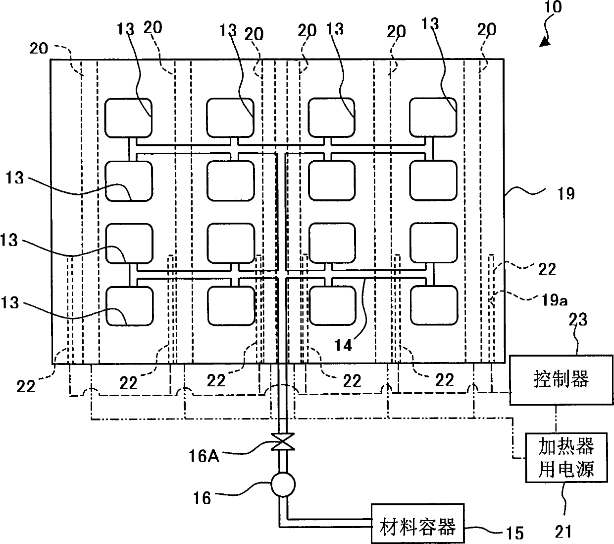
[0097] Example 1): Using the magnetic field forming device 10 shown in FIG. 2, the temperature T1 of the female mold 19 is set to 50°C by the heater member 20, and the formed body is sintered after performing magnetic field forming to obtain a ferrite magnet. .

Embodiment 2

[0098] Example 2): Using the magnetic field forming device 10, the temperature T1 of the female mold 19 was set to 60° C. by the heater member 20, and the formed body was sintered after performing magnetic field forming to obtain a ferrite magnet.

Embodiment 3

[0099] Example 3): Using the magnetic field forming device 10, the temperature T1 of the female mold 19 is set to 100° C. by the heater member 20, performing magnetic field forming, and then sintering the formed body to obtain a ferrite magnet.


PUM

PropertyMeasurementUnit
viscosity indexaaaaaaaaaa

Abstract

An object of the present invention is to provide a magnetic field shaping device, a ferrite magnet manufacturing method, etc., which can improve the yield of the manufacturing process and stabilize the quality. When performing magnetic field shaping, a female mold (19) having a plurality of mold cavities (13) is heated to a predetermined temperature by a heater member (20) under the control of a controller (23). As the heating temperature, it is preferable to control with the controller (23) so that the temperature (T1) of the female mold (19) detected by the sensor (22) is 40°C or more. In this way, by heating the female mold (19), the temperature of the molding slurry in the cavity (13) can be increased, so that the dehydration property can be improved, and the yield of the product can be improved.

Description

technical field [0001] The present invention relates to a magnetic field shaping device, a method for manufacturing ferrite magnets and metal molds for them. Background technique [0002] When manufacturing ferrite (sintered) magnets that have become the mainstream of magnets, the raw materials are mixed in a predetermined ratio, and then calcined to ferrite, and then the obtained calcined body is crushed to a submicron size to obtain Finely pulverized powder composed of ferrite particles. Next, the finely pulverized powder is compression-molded through a metal mold in a magnetic field (hereinafter referred to as magnetic field forming) to obtain a molded body, and the molded body is sintered to obtain a ferrite magnet. [0003] The magnetic field forming process can be broadly classified into a dry process in which the material is dried and then formed, and a wet process in which the material is formed into a slurry. [0004] In the case of magnetic field forming by a wet...

Claims


Application Information

Patent Timeline
Patent Type & Authority Applications(China)
IPC IPC(8): H01F41/02B28B3/02B30B11/00B30B11/02C04B35/622H01F1/113
CPCC04B35/622H01F1/113H01F41/0266
Inventor 增泽清幸栗田英生大塚正幸永塚康弘田口仁
Owner TDK CORPARATION
Why Eureka
Try Eureka