Computed tomography scanning

A scanner, CT scanning technology, applied in the field of computed tomography scanning, can solve problems such as inability to measure motion

Active Publication Date: 2006-01-18
ELEKTA AB
View PDF0 Cites 3 Cited by
  • Summary
  • Abstract
  • Description
  • Claims
  • Application Information

AI Technical Summary

Problems solved by technology

Also, motion cannot be measured on reconstructed volumetric data

Method used


Image

  • Computed tomography scanning
  • Computed tomography scanning
  • Computed tomography scanning

Examples


Embodiment Construction

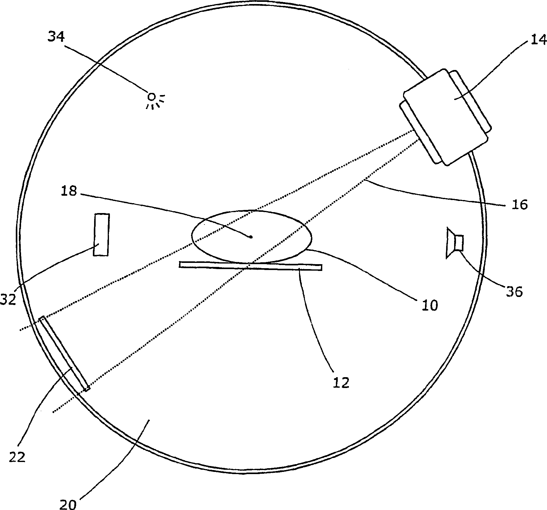
[0017] figure 1 A cone-beam CT scanner is shown. The patient 10 rests on a support board 12, which may be of any suitable design. The support plate can usually adjust the patient's pitch position and longitudinal position, and according to requirements, this is guaranteed.

[0018] An x-ray source 14 is arranged to project a broad beam of radiation 16 aimed at an isocenter 18 of the patient. The x-ray source 14 can be rotated about the isocenter 18 on the swivel bearing 20 . For example, the support may be in the form of a ring or ring surrounding the patient 10 and support plate 12 on which the radiation source is mounted, or it may be a C-arm, or any suitable support that allows the radiation source to rotate, or their random combination.

[0019] A two-dimensional flat-panel detector 22 is also installed on the support 20 , it faces the radiation source 14 , and the two-dimensional flat-panel detector 22 is arranged so as to rotate synchronously with the radiation sourc...


PUM


Abstract

By applying the related technology of respiration on the received projection image, the artifact of the reconstruction body data of the CT system with conical beam can be eliminated. Therefore, the respiratory phase of patients can be monitored during the continuous obtaining of the projection image. After completion of the obtaining, the centralized selection of the projection image with comparable respiratory phase is carried out, and then the same technology with that of the traditional CT is adopted for utilizing the reconstruction body data. The invention can randomly select the phase and research the role of respiration. The invention can also utilize the characteristics of each projection image, such as the diaphragm of patients to determine the respiratory phase. The invention can utilize the characteristics of the projection image to control the sending of the radioactive rays for treatment according to the breathing cycle of patients, thereby ensuring the correct location of tumor while sending the radioactive rays.

Description

technical field [0001] The present invention relates to scanning using computed tomography (CT). Background technique [0002] A CT scan is the process of imaging a patient's internal structures. In a traditional CT scan, a beam of X-rays is projected through the patient and its attenuation is measured. At the same time, the device is rotated about an axis passing longitudinally through the patient. Thus, data are acquired on the attenuation of the beam in each direction in the plane of rotation. From this data, the internal structure of the patient in this plane can be calculated. The patient or device angle is then translated along this axis, after which the next plane (called a "slice") is probed. Then, from the various slices, a 3D image of the patient is constructed. [0003] One problem is that the patient is immobile for the time required to obtain the necessary slices. Visible motor movement can be avoided by properly instructing the patient, but, even then, ea...

Claims


Application Information

Patent Timeline
IPC IPC(8): A61B6/03A61B5/113A61N5/10A61B6/00G06T11/00
CPCA61B6/541A61B6/032G06T11/005G06T2211/412A61B5/0816A61B6/03A61B6/04G06T11/003
Inventor 凯文·J.·布朗戴维·加弗雷杰弗里·斯维德森马塞尔·凡赫科詹-加科布·索科
Owner ELEKTA AB
Why Eureka
Try Eureka