
Kitchen refuse processing apparatus

A kitchen waste and treatment device technology, applied in the field of kitchen waste treatment devices, can solve problems such as damage to a spray pipe of a treatment tank, and achieve the effects of easy replacement, prevention of damage, and reduction in usage.

Inactive Publication Date: 2006-01-18
裵三俊
View PDF0 Cites 13 Cited by
  • Summary
  • Abstract
  • Description
  • Claims
  • Application Information

AI Technical Summary

Problems solved by technology

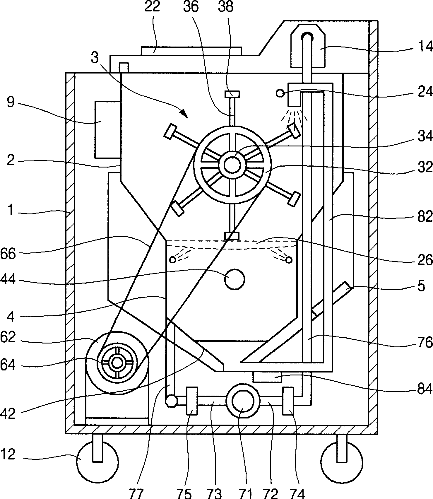
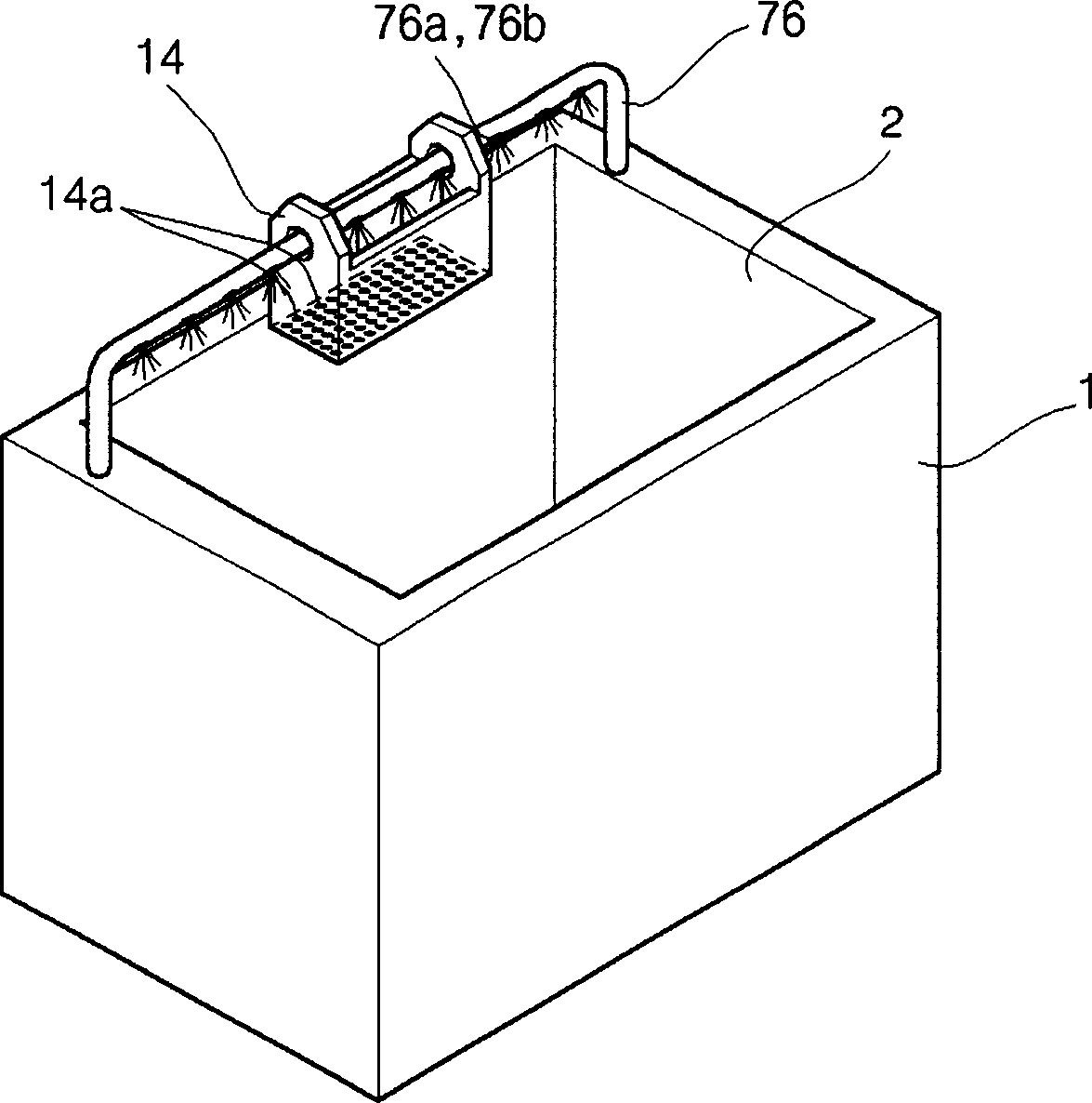
[0007] In the conventional kitchen waste treatment equipment, the treatment tank spray pipe of the water supply mechanism that supplies water to the treatment tank is only formed inside the treatment tank, so it interferes with the stirring blades of the mixer, and there is a problem that the treatment tank spray pipe is damaged

Method used


Image

  • Kitchen refuse processing apparatus
  • Kitchen refuse processing apparatus
  • Kitchen refuse processing apparatus

Examples


Embodiment Construction

[0034] Hereinafter, preferred embodiments of the present invention will be described in detail with reference to the drawings.

[0035] figure 1 It is a cross-sectional view showing a kitchen waste treatment device according to an embodiment of the present invention, and includes a treatment tank 2, a mixer 3, a drainage tank 4, a heating mechanism 5, a control panel 9 serving as a stirring mechanism, a drainage mechanism, a water resupply mechanism, and a control mechanism etc. are provided inside the casing 1 having a predetermined shape.

[0036] A plurality of rotatable casters 12 are provided on the bottom surface of the housing 1 .

[0037] The above-mentioned treatment tank 2 is arranged at the upper end of the inside of the housing 1 , a mixer 3 is arranged inside the above-mentioned treatment tank 2 , and a drainage tank 4 is provided in communication with the bottom of the treatment tank 2 .

[0038] An openable and closable cover 22 is provided on the above-mentio...


PUM


Abstract

This invention provides treatment device for kitchen residual garbage to recycle the unresolved particle kitchen residual garbage to treatment tank for aftertreatment and increase efficiency greatly and comprises shell for device surface, a treatment tank, a mixer, a mixture mechanism for rotating the mixer, a dewater tank, a feed-water mechanism to feed water for treatment tank and dewater tank in some time interval and adjust hydrosphere environment of treatment tank and keep clear state of dewater tank, a circulating mechanism used to take micronized garbage and water to treatment tank, a heat mechanism, a control mechanism to control all operations on garbage decomposition.

Description

technical field [0001] The present invention relates to a kitchen waste treatment device, and more specifically relates to the recycling of the undecomposed particulate kitchen waste in the kitchen waste once treated in the treatment tank to the treatment tank for further treatment, so that the treatment efficiency of the kitchen waste is extremely high Improved kitchen waste disposal device. Background technique [0002] The kitchen waste treatment device of the prior art uses a mixer to stir the kitchen waste in the treatment tank, and puts in microorganisms to ferment and decompose it, and then flows into the drainage tank from the perforated plate arranged at the lower end of the treatment tank. At this time, the kitchen waste flows in in a mixed state of completely decomposed liquefied substances and undecomposed micronized kitchen waste and water. However, in the prior art, there is a problem in that completely decomposed kitchen waste and micronized kitchen waste are...

Claims


Application Information

Patent Timeline
IPC IPC(8): B09B3/00
Inventor 裵三俊
Owner 裵三俊
Learn More