
Pulley rolling equipment

A technology of rolling equipment and pulleys, which is applied in the field of pulley rolling equipment, can solve problems such as insufficient rigidity, and achieve the effects of reasonable structure, durable rope grooves, and high accuracy

Inactive Publication Date: 2006-01-11
HUNAN INSTITUTE OF ENGINEERING
View PDF0 Cites 4 Cited by
  • Summary
  • Abstract
  • Description
  • Claims
  • Application Information

AI Technical Summary

Problems solved by technology

This kind of pulley has the advantages of light weight, convenient maintenance, and prolonging the service life of the wire rope. However, like other riveted pulleys, its rigidity is insufficient, and the riveted part is difficult to avoid loosening is its inherent disadvantage.

Method used


Image

  • Pulley rolling equipment
  • Pulley rolling equipment
  • Pulley rolling equipment

Examples


Embodiment Construction

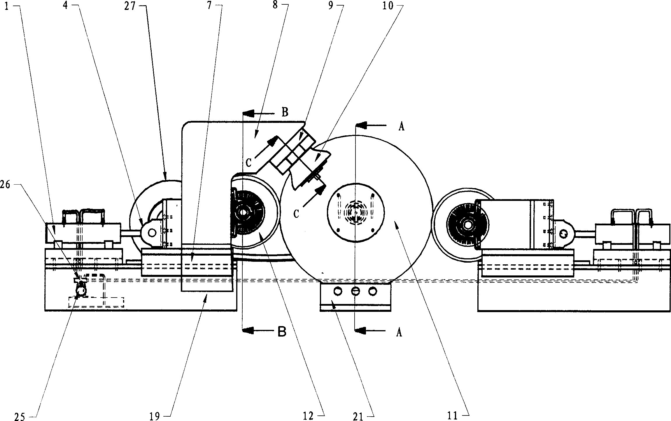
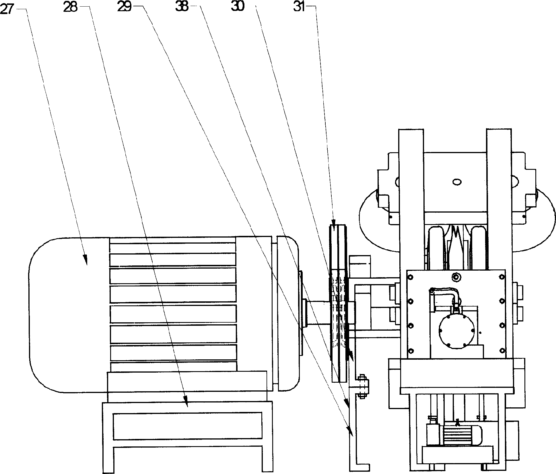
[0019] like figure 1 , figure 2 , image 3 , Figure 4 , Figure 5 , Image 6 Shown, pulley rolling equipment, it is made up of main frame 19 and main shaft frame 38, motor 27, workpiece supporting mechanism, wheel groove rolling and forming mechanism, wheel rim rolling and forming mechanism 12, hydraulic mechanism 1, heating device 37 and temperature control device;

[0020] like figure 2 , image 3 As shown, the main frame 19 and the main shaft frame 38 are fixedly installed on the same horizontal plane, the main shaft frame 38 includes the lower frame 29 and the upper frame 30, the main shaft 33 and the workpiece supporting mechanism are all installed on the upper frame 30, wherein the main shaft The main bearing 34 of 33 is fixedly installed on the connecting plate 39, and the main shaft 33 is installed in the main bearing housing 40 and the main bearing cover 32; It is fixedly installed on one side of the shaft shoulder of the main shaft 33, and the workpiece 11...


PUM


Abstract

A pulley rolling machine is composed of main machine frame, mainshaft supporting frame, motor, workpiece bearing mechanism, annular recess rolling-shaping unit, wheel rims rolling-shaping unit, hydraulic unit, heating unit and temp controller.

Description

technical field [0001] The invention relates to a pulley rolling equipment. Background technique [0002] At present, the manufacturing methods of pulleys in my country mainly include casting, riveting, welding, stamping, rolling and other methods. Although casting pulleys have insurmountable shortcomings, casting methods are still the main method in my country, and riveting and rolling methods are developed recently. new pulley manufacturing method. [0003] Casting pulleys are typical traditional pulleys. In developed countries, such pulleys are in a situation of being eliminated due to many shortcomings such as brittleness, cracking, large wire rope wear, and unsafety. The scope of use of this kind of pulley in our country is becoming more and more limited, and new pulley manufacturing methods have been emerging. [0004] The riveted pulley is a pulley produced by a new manufacturing method. It is formed by pressing two steel plates. It is one of the replacement products...

Claims


Application Information

Patent Timeline
Patent Type & Authority Applications(China)
IPC IPC(8): B21H1/04
Inventor 傅彩明刘迎春
Owner HUNAN INSTITUTE OF ENGINEERING
Learn More