
Pouring weight loaded buffering mechanism

A buffer mechanism and heavy block technology, applied in the field of buffer mechanism, can solve problems such as failure to achieve unloading purpose, and achieve the effect of reliable operation, wide application range and simple structure

Inactive Publication Date: 2005-12-28
甘建国
View PDF0 Cites 8 Cited by
  • Summary
  • Abstract
  • Description
  • Claims
  • Application Information

AI Technical Summary

Problems solved by technology

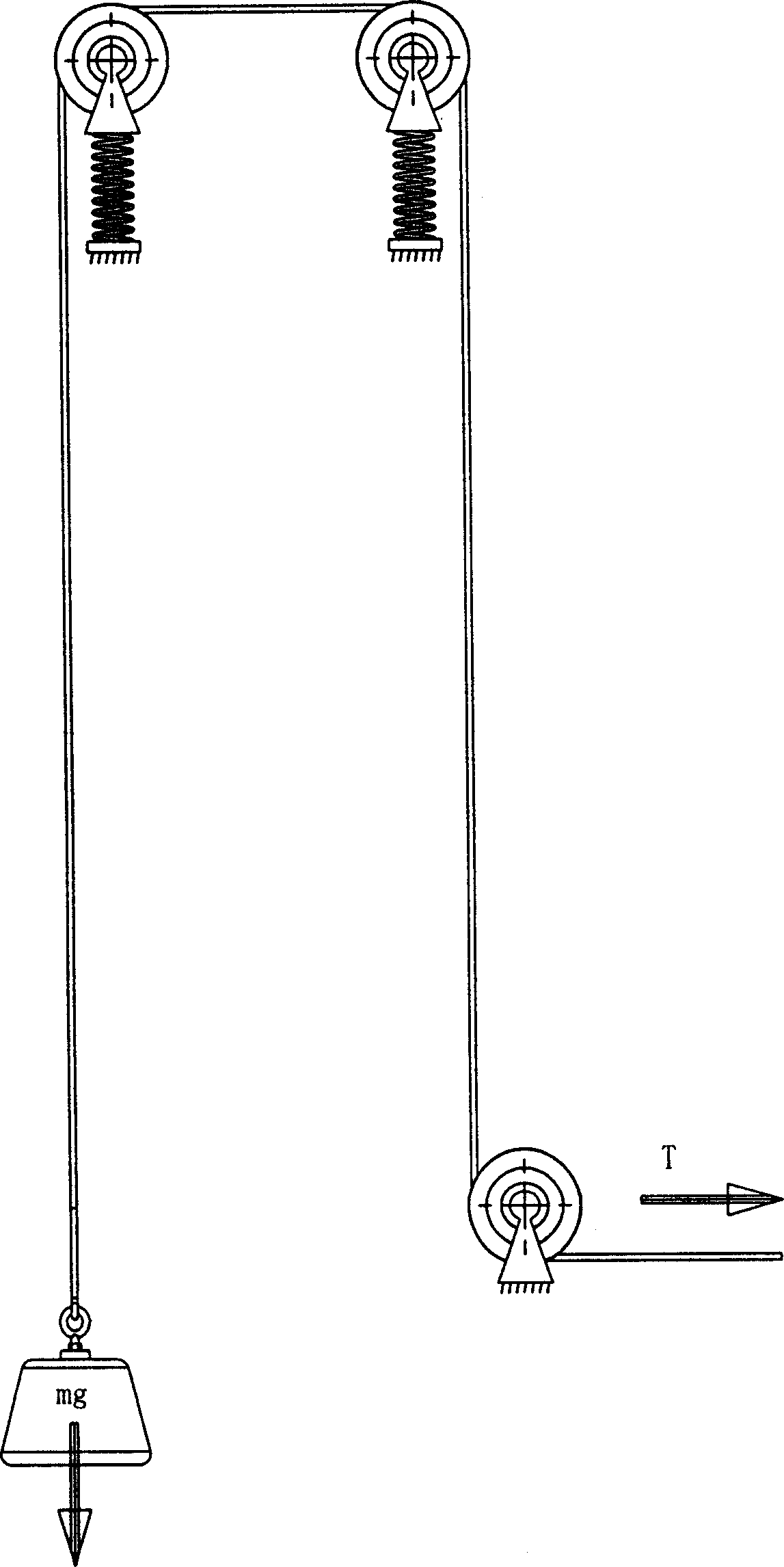
like image 3 In the schematic diagram of the weight loading mechanism shown, the spring set under the support of the pulley has a certain buffering effect, but it cannot achieve the real purpose of unloading

Method used


Image

  • Pouring weight loaded buffering mechanism
  • Pouring weight loaded buffering mechanism
  • Pouring weight loaded buffering mechanism

Examples


Embodiment Construction

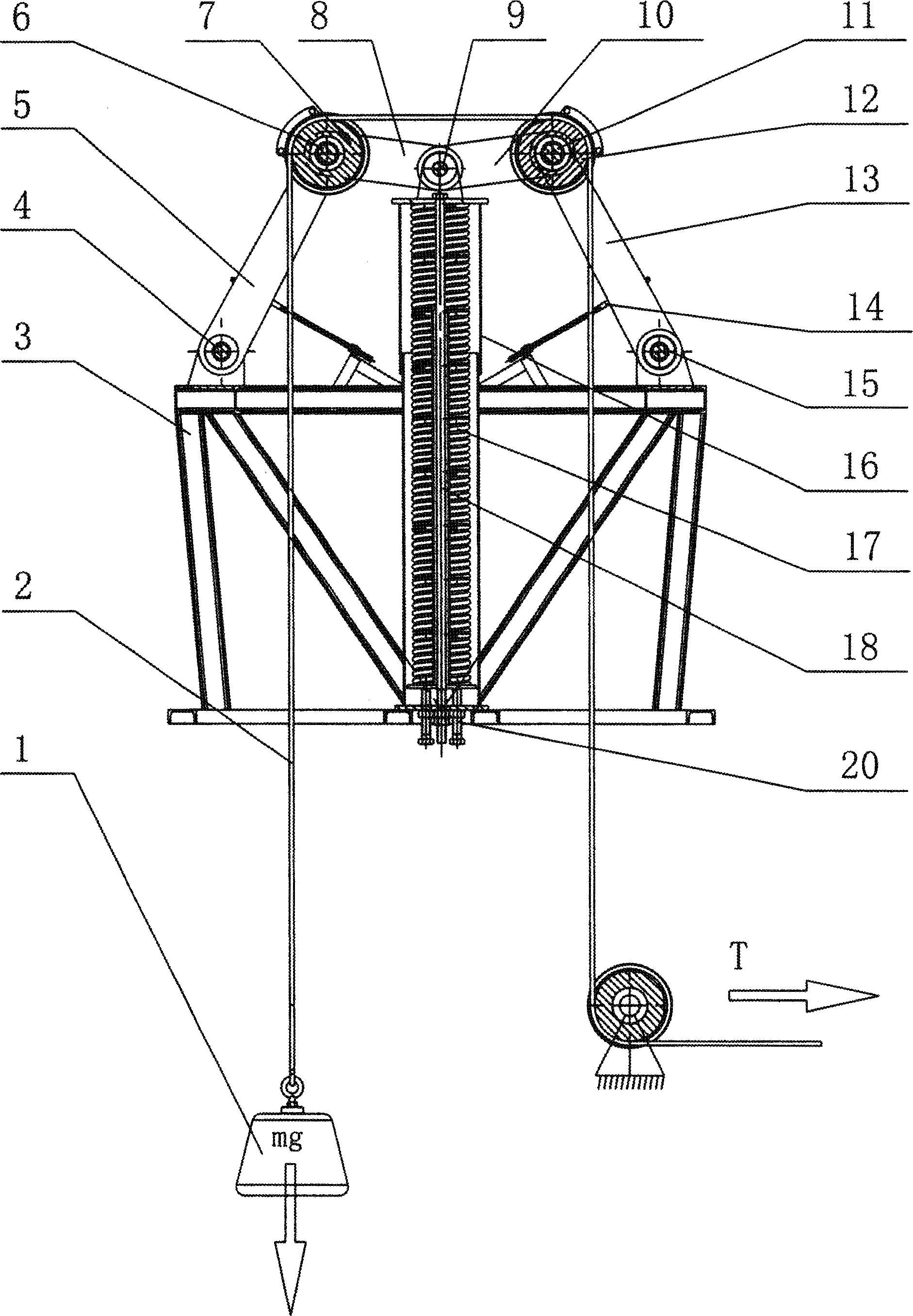
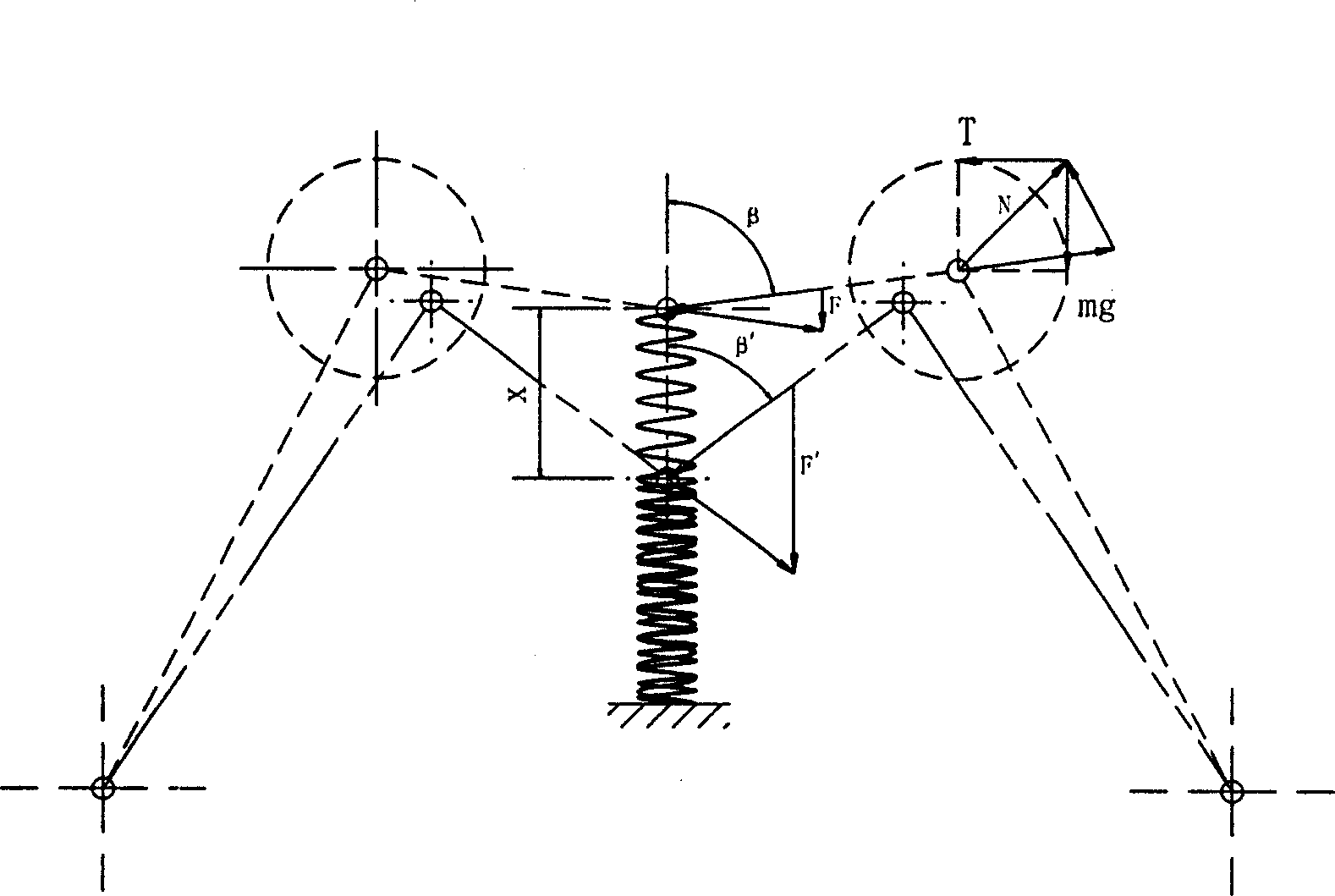
[0018] see figure 1 One end of the left connecting rod 5 and the right connecting rod 13 are respectively arranged symmetrically with the frame 3 to be hinged, and the other ends of the left connecting rod 5 and the right connecting rod 13 are connected with the upper left connecting rod 8 and the upper right through the left shaft 6 and the right shaft 11 respectively. One end of the rod 10 is hinged, the left shaft 6 and the right shaft 11 are respectively provided with a left pulley 7 and a right pulley 12, the other ends of the left upper link 8 and the right upper link 10 are hinged with the spring seat 16 through the central shaft 9, and the combined spring 17 is installed Between the frame 3 and the spring seat 16, one end of the long screw 18 is connected to the frame 3, and the other end is connected to the spring seat 16 to adjust the spring pressure; the adjusting bolt 20 is installed at the bottom of the frame 3 to adjust the combined spring 17 , central axis 9, a...


PUM


Abstract

A weight loaded buffering mechanism features that the left and right connecting rods are symmetrically pivoted to machine frame, their other ends are pivoted via left and right axles to the left and right upper connecting rods, said left and right axles have respective left and right pulleys, and said left and right upper connecting rods are respectively pivoted via middle axle to the spring unit on machine frame. It has a constant buffer action.

Description

technical field [0001] The invention relates to a buffer mechanism, in particular to a heavy-block-loaded buffer mechanism required by an operating machine that applies a force to materials in a heavy-block loading manner. Background technique [0002] In the chemical industry, metallurgy, mining, building materials and other industrial sectors, some operating machinery often needs to exert a certain force on the processed materials, such as grinding machinery. The loading methods generally include spring loading, hydraulic cylinder loading and weight loading. In the process of pressure-loaded operations, affected by various working conditions, it is necessary for the pressure to be able to retreat, and this pressure retreat and restoration often occurs in an instant, resulting in a large acceleration, which is harmful to components and transmissions. Mechanisms generate very large shock loads. The ideal state is that no matter how much the acceleration is,...

Claims


Application Information

Patent Timeline
Patent Type & Authority Applications(China)
IPC IPC(8): B02C23/00
Inventor 甘建国
Owner 甘建国
Learn More