A fixed hoist hoist applied to self-discharging gates
A hoisting and hoisting machine technology, applied in marine engineering, construction, barrage/weir, etc., can solve the problems of the end of the life of the speed-regulating motor and the difficulty in realizing the opening and closing of the variable-speed control gate, and achieve the effect of convenient switching control.
- Summary
- Abstract
- Description
- Claims
- Application Information
AI Technical Summary
Problems solved by technology
Method used
Image
Examples
Embodiment 1
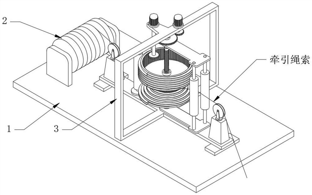
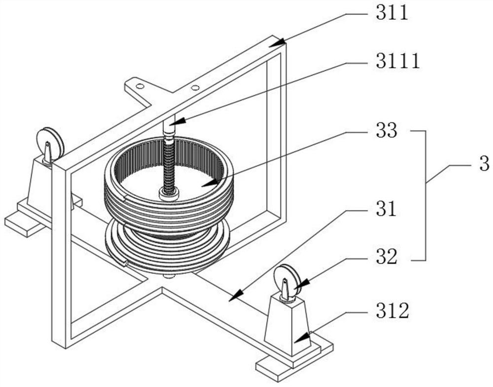
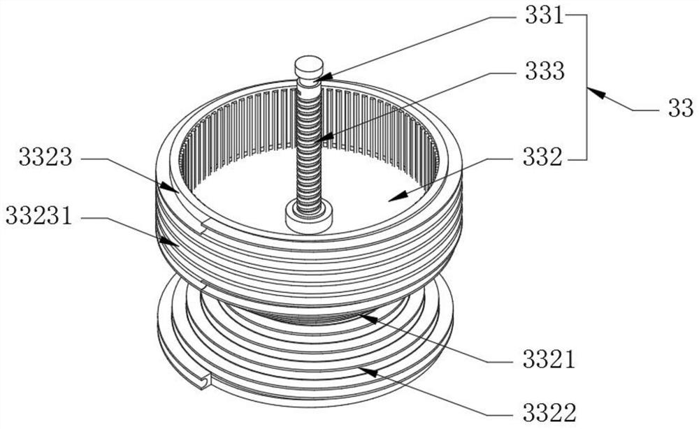
[0031] see Figure 1-3 with Figure 5 , a fixed hoist hoist applied to self-discharging gates, including a base 1 and a winding drum 2, the winding drum 2 is used to wind the traction rope, the base 1 is fixedly equipped with a wire climbing buffer device 3, the wire Climbing buffer device 3 comprises bearing plate 31, pulley 32 and guide wheel 33, and pulley 32 is used for guiding traction rope, and the upper end face of bearing plate 31 is fixedly connected with rectangular frame 311 in the middle, and guide wheel 33 is positioned at rectangular frame 311, The upper end surface of the bearing plate 31 is fixedly connected with a support platform 312 on both sides of the rectangular frame 311, the wheel seat on the pulley 32 is connected to the top of the support platform 312 in rotation, and the winding drum 2 is located on one side of one of the pulleys 32. The traction rope on the drum 2 passes through two pulleys 32, and contacts with the outer wall of the guide wheel 33...
Embodiment 2
[0033] see figure 2 with Figure 4 The difference from Embodiment 1 is that it also includes an off-line device 4 and a drive assembly 5. The off-line device 4 includes a portal frame 41 and a rotary sleeve 42. The fixedly connected positioning shaft 3111, the free ends of the two opposite connecting plates 411 on the portal frame 41 are correspondingly connected to the two positioning shafts 3111 in rotation, and the rotating sleeve 42 is rotatably connected to the connecting beam 412 between the two connecting plates 411 Above, the winding drum 2 and the gantry 41 are located on both sides of the rectangular frame 311. When the gantry 41 rotates to one side, the rotating sleeve 42 pushes the traction rope away from the entire guide wheel 33, and at this time, the constant-speed take-up and pay-off can be realized. That is to say, the opening and closing process of the gate is constant speed, which is suitable for occasions requiring constant speed control to control the open...
Embodiment 3
[0035] see Figure 4 with Figure 5 , based on the difference between Embodiment 1 and Embodiment 2, there are two connecting beams 412 between the two connecting plates 411 on the gantry 41, and each connecting beam 412 is rotatably connected to a swivel 42 to pull the rope Located between the two rotary sleeves 42, the upper end surface of the upper end surface of the bearing plate 31 and the other side of the rectangular frame 311 are rotatably connected with a vertically distributed spacing roller 8, and the traction rope bypasses the spacing roller 8, two guides The center of rotation of the pulley 32 wheel seat and the V-shaped sheave 332 is on the same plane, and when the two swivel sleeves 42 follow the gantry 41 to rotate and cooperate with the limit roller 8, the contact area between the winding rope and the guide wheel 33 can be increased. This can increase the difference between the minimum speed and the maximum speed of the gate movement.
[0036] Working princi...
PUM
 Abstract
Description
Claims
Application Information
 - R&D Engineer
- R&D Manager
- IP Professional
- Industry Leading Data Capabilities
- Powerful AI technology
- Patent DNA Extraction
Browse by: Latest US Patents, China's latest patents, Technical Efficacy Thesaurus, Application Domain, Technology Topic, Popular Technical Reports.
© 2024 PatSnap. All rights reserved.Legal|Privacy policy|Modern Slavery Act Transparency Statement|Sitemap|About US| Contact US: help@patsnap.com


