
Universal shaft

A technology of cardan shaft and petal, applied in the field of cardan shaft, can solve the problems of small contact area, short service life, large contact stress of meshing pair, etc., and achieve the effect of large contact area and long service life

Inactive Publication Date: 2018-07-13
钟文楚
View PDF0 Cites 0 Cited by
  • Summary
  • Abstract
  • Description
  • Claims
  • Application Information

AI Technical Summary

Problems solved by technology

[0002] At present, a known cardan shaft is composed of four "Ω" shaped petals and two supporting balls. During operation, only a certain part of a pair of teeth contacts each other, the contact area is small, and the contact stress of the meshing pair is large; During operation, the same pair of teeth sometimes contacts and sometimes disengages, which is prone to impact loads, fast wear and short service life

Method used


Image

  • Universal shaft
  • Universal shaft
  • Universal shaft

Examples


Embodiment 1

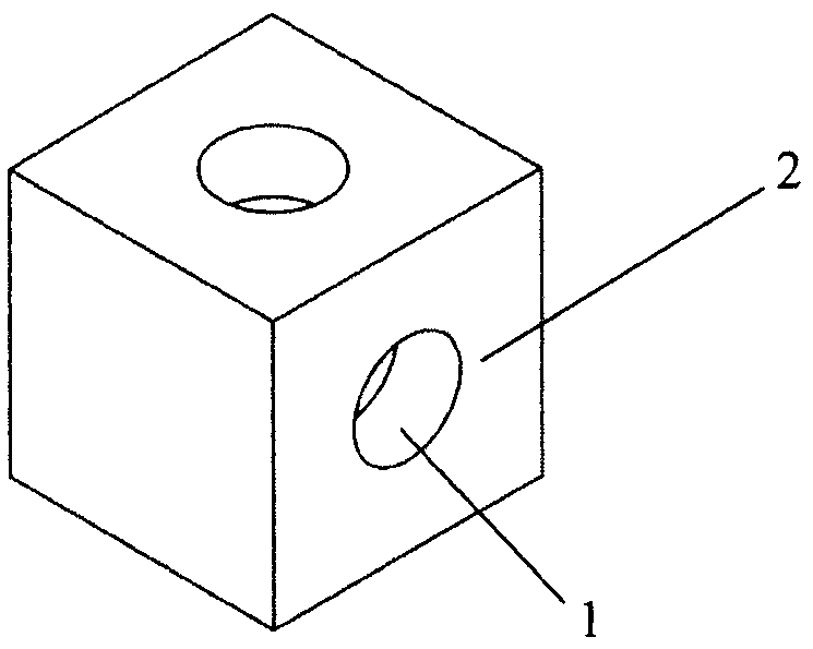
[0015] Such as figure 2 As shown, the shape of the slider (8) is a cube, and except for the two opposite faces, there is a hole (1) for assembling a positioning pin on each of the other four faces, and the axis of the hole (1) is located at the center of the square. And perpendicular to the plane (2) where the square lies. Such as Figure 4 As shown, there is a gap on the petal body (7), the two sides of the gap are two parallel planes (4), the size of the gap is just equal to or slightly larger than the side length of the slider (8), on both sides of the gap Each has a hole (5) for assembling a positioning pin, these two holes (5) are coaxial, and the axes of the holes (5) are perpendicular to the two parallel planes (4) on both sides of the gap. Such as Figure 6 As shown, two petal bodies (7) in the middle are contained on the intermediate shaft (10), guarantee that these two petal bodies (7) are on the same axis (or these three parts are made into one). Put the slider...

Embodiment 2

[0017] The structure is similar to the first embodiment, only the positioning pin (9) and the slider (8) are fixed, the positioning hole (5) on the petal body (7) is changed into a short groove (6), the groove (6) The direction is consistent with the axis of the petal body (7). Its effect is: if the petal body (7) of upper and lower end has slight axial displacement, positioning pin (9) can slide in groove (6) without force, still can play positioning effect.

Embodiment 3

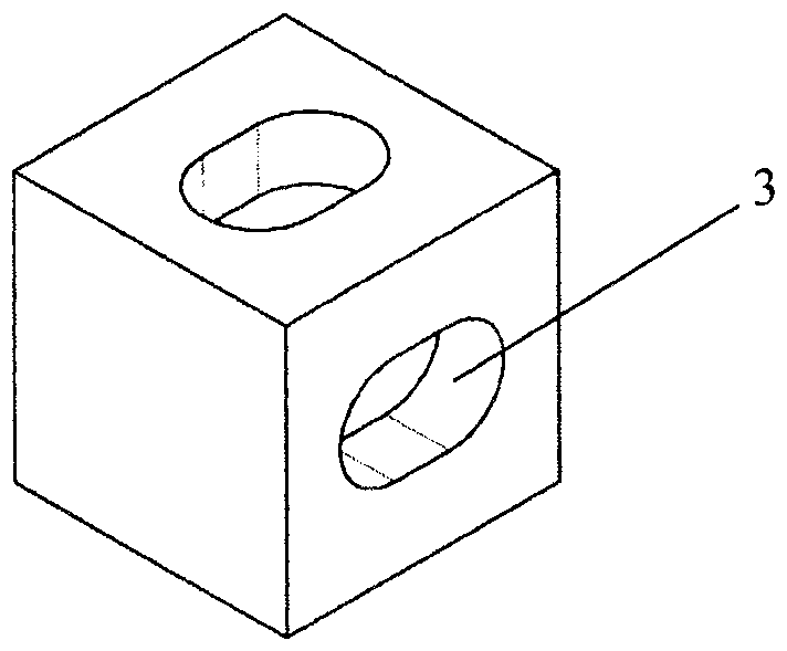
[0019] The structure is similar to that of Embodiment 1, except that the positioning pin (9) and the petal body (7) are fixed, and the positioning hole (1) on the slider (8) is changed into a short groove (3), and the groove (3) The direction is consistent with the axis of the cardan shaft. Its effect is: if the petal body (7) of upper and lower end has slight axial displacement, positioning pin (9) can slide in groove (3) without force, still can play positioning effect.


PUM


Abstract

The invention provides a universal shaft. At present, a commonly known universal shaft is composed of four inverted-U-shaped pedal bodies, two supporting balls and the like, and thus being high in contact stress and prone to generating impact load. The engagement pair of the universal shaft is low in contact stress and is free of impact load. The universal shaft is composed of four pedal bodies, two sliding blocks and eight locating pins. Each sliding block is in the shape of a cube. One notch is formed in each pedal body. Two parallel planes are arranged on the two sides of each notch. The dimension of each notch is just equal to the border length of each cube. The notch of one pedal body is clamped to the two opposite planes of the sliding blocks, another pedal body is arranged coaxiallywith the first pedal body or with a small angle between, the notch of the second pedal body is clamped to the other two opposite planes of the sliding blocks, as a result, when one of the pedal bodies rotates in the axial direction, the torque can be transmitted to the corresponding sliding block because the two sides of the pedal body make contact with the two opposite planes on the sliding blocks, and then the sliding block transmits the torque to the other pedal body.

Description

technical field [0001] The invention relates to a cardan shaft, especially a cardan shaft of a screw drilling tool. Background technique [0002] At present, a known cardan shaft is composed of four "Ω"-shaped petal bodies and two supporting balls. When working, only a certain part of a pair of teeth contacts each other, the contact area is small, and the contact stress of the meshing pair is large; During operation, the same pair of teeth sometimes contacts and sometimes disengages, which is prone to impact loads, fast wear and short service life. Contents of the invention [0003] The technical problem to be solved by the present invention is: to provide a cardan shaft with large contact area during operation and small contact stress of the meshing pair; during operation, the meshing pair is always in contact without disengagement and has no impact load. [0004] The technical scheme that the present invention takes for solving above technical problem is: [0005] The ...

Claims


Application Information

Patent Timeline
IPC IPC(8): F16D3/26E21B17/02
CPCF16D3/26E21B17/03
Inventor 不公告发明人
Owner 钟文楚
Learn More