Sheathing heater,its mfg. method and heater
A heater and sheath technology, applied in the directions of water heaters, fluid heaters, heating element shapes, etc., can solve the problem of long processing steps of sheath heaters, poor mechanical impact resistance of glass sealing materials, and expansion of manufacturing costs, etc. problems, to achieve cheap safety, maintain usability, and simplify the manufacturing process
- Summary
- Abstract
- Description
- Claims
- Application Information
AI Technical Summary
Problems solved by technology
Method used
Image

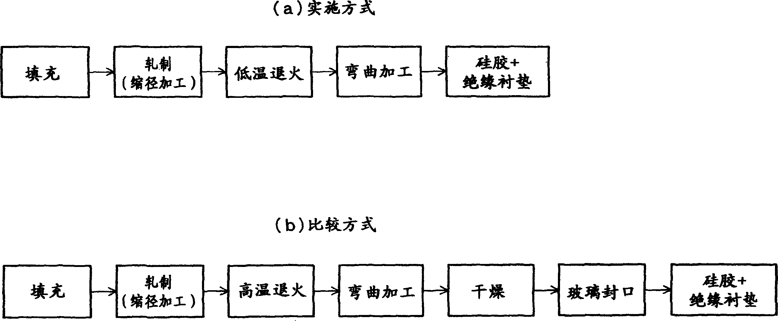
Examples
Embodiment approach 1
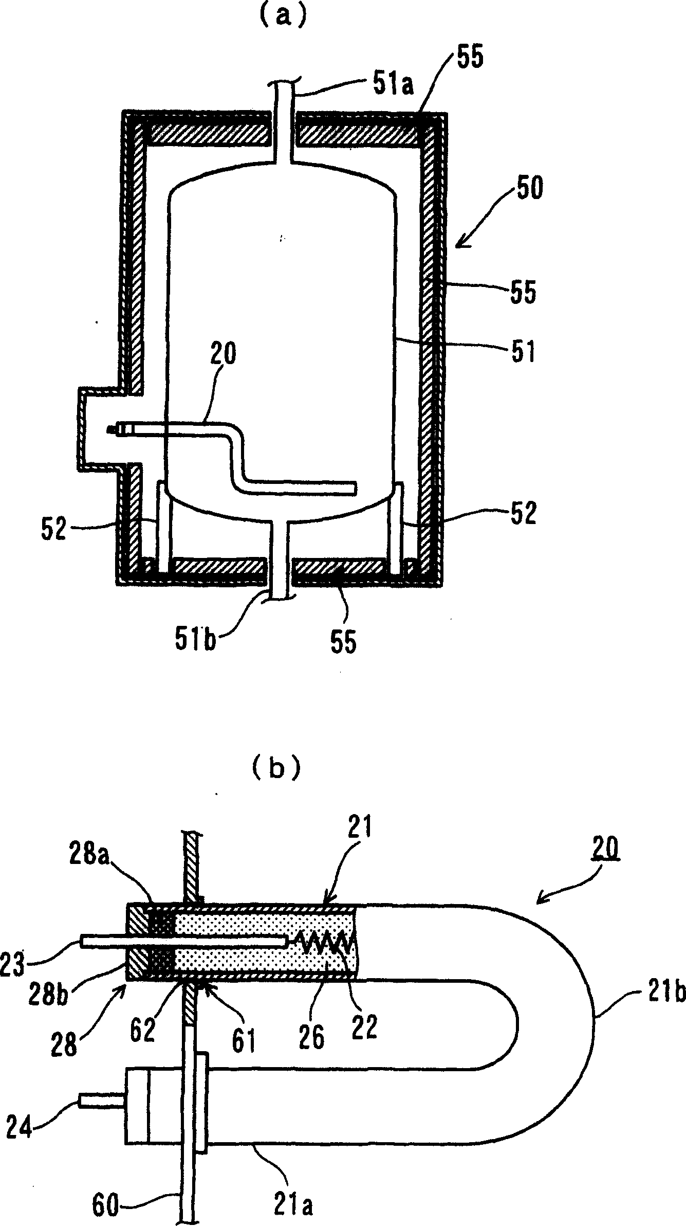
[0037] figure 2 (a) shows embodiment of the electric water heater to which the sheath heater of this invention was attached.
[0038] In this figure, the electric water heater 50 supports the water storage tank 51 by the water storage tank bracket 52, while the hot water outlet pipe 51a is connected to the upper part of the water storage tank 51, and the water inlet pipe 51b is connected to the lower part thereof. While the sheath heater 20 is arranged in the water tank 51 , the sheath heater 20 is fixed on the outer wall of the water storage tank 51 to heat the water stored in the water storage tank 51 .
[0039] And the reference numeral 55 is in order to heat the heat preservation material for the water storage tank 51 and cover around the water storage tank 51 .
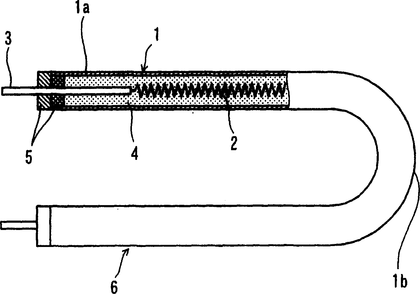
[0040] as figure 2 As shown in (b), in this embodiment, the sheath heater 20 is inserted into the metal pipe 21 while the coil-shaped heating wire 22 connected to the terminal rods 23 and 24 is inserted at bo...
PUM
 Abstract
Description
Claims
Application Information
 - R&D
- Intellectual Property
- Life Sciences
- Materials
- Tech Scout
- Unparalleled Data Quality
- Higher Quality Content
- 60% Fewer Hallucinations
Browse by: Latest US Patents, China's latest patents, Technical Efficacy Thesaurus, Application Domain, Technology Topic, Popular Technical Reports.
© 2025 PatSnap. All rights reserved.Legal|Privacy policy|Modern Slavery Act Transparency Statement|Sitemap|About US| Contact US: help@patsnap.com