


Quick Research
Generate reliable direction feasibility study reports for your R&D in just a few steps.

Technical Q&A
Discover and master advanced knowledge NOW. Basics, ideas, possibilities, all at once.

Find Solutions
As an expert in R&D theories, this can generate solutions to your technical problems instantly.

Evaluate Feasibility
Analyze your overall solution with one click, know your potential R&D risks in advance.

Monitor Landscape
Get weekly tech updates, stay abreast of the latest tech innovations and key insights.
System and method for accessing vital data from memory
A memory system and memory access technology, which is used to ensure error-free access to key data fields stored in memory when the system is powered on, and can solve problems such as difficult to preset delay time, errors, and insufficient data access voltage.
- Summary
- Abstract
- Description
- Claims
- Application Information
AI Technical Summary
Problems solved by technology
Method used
Image


Examples
Embodiment Construction
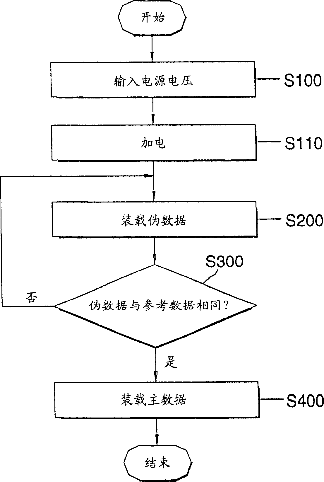
[0026] figure 1 A block diagram of a memory system according to an embodiment of the invention is shown. refer to figure 1 , the memory system 10 includes a memory 100 , a controller 300 and a reference data storage device 200 . The memory 100 has a main area 101 for storing main data, which is data crucial to the operation of the memory system. Examples of master data are boot code, BIOS code, or operating system code, among others. The memory 101 also includes a dummy area 102 for storing test data (hereinafter referred to as "dummy data"), which is data for testing the readiness of an applied voltage as described further below. Dummy data is also stored in the reference data storage 200 . Controller 300 includes a processor (not shown) for controlling the operation of the memory system, including retrieving data from memory 100 and from reference data storage 200 . When the memory system 10 is turned on for the first time, or when there is a power-on reset operation, t...
PUM
 Abstract
Description
Claims
Application Information
 - R&D Engineer
- R&D Manager
- IP Professional
- Industry Leading Data Capabilities
- Powerful AI technology
- Patent DNA Extraction
Browse by: Latest US Patents, China's latest patents, Technical Efficacy Thesaurus, Application Domain, Technology Topic, Popular Technical Reports.
© 2024 PatSnap. All rights reserved.Legal|Privacy policy|Modern Slavery Act Transparency Statement|Sitemap|About US| Contact US: help@patsnap.com