Adaptive CFL control circuit
A technology for controlling circuits and circuits, applied in control/regulating systems, regulating electrical variables, and the use of gas discharge lamps, etc., can solve problems such as damage to ballast output stage components, lack of tolerance, and lack of fault handling resilience. Achieving the effect of simple cost and low cost
- Summary
- Abstract
- Description
- Claims
- Application Information
AI Technical Summary
Problems solved by technology
Method used
Image
Examples
Embodiment Construction
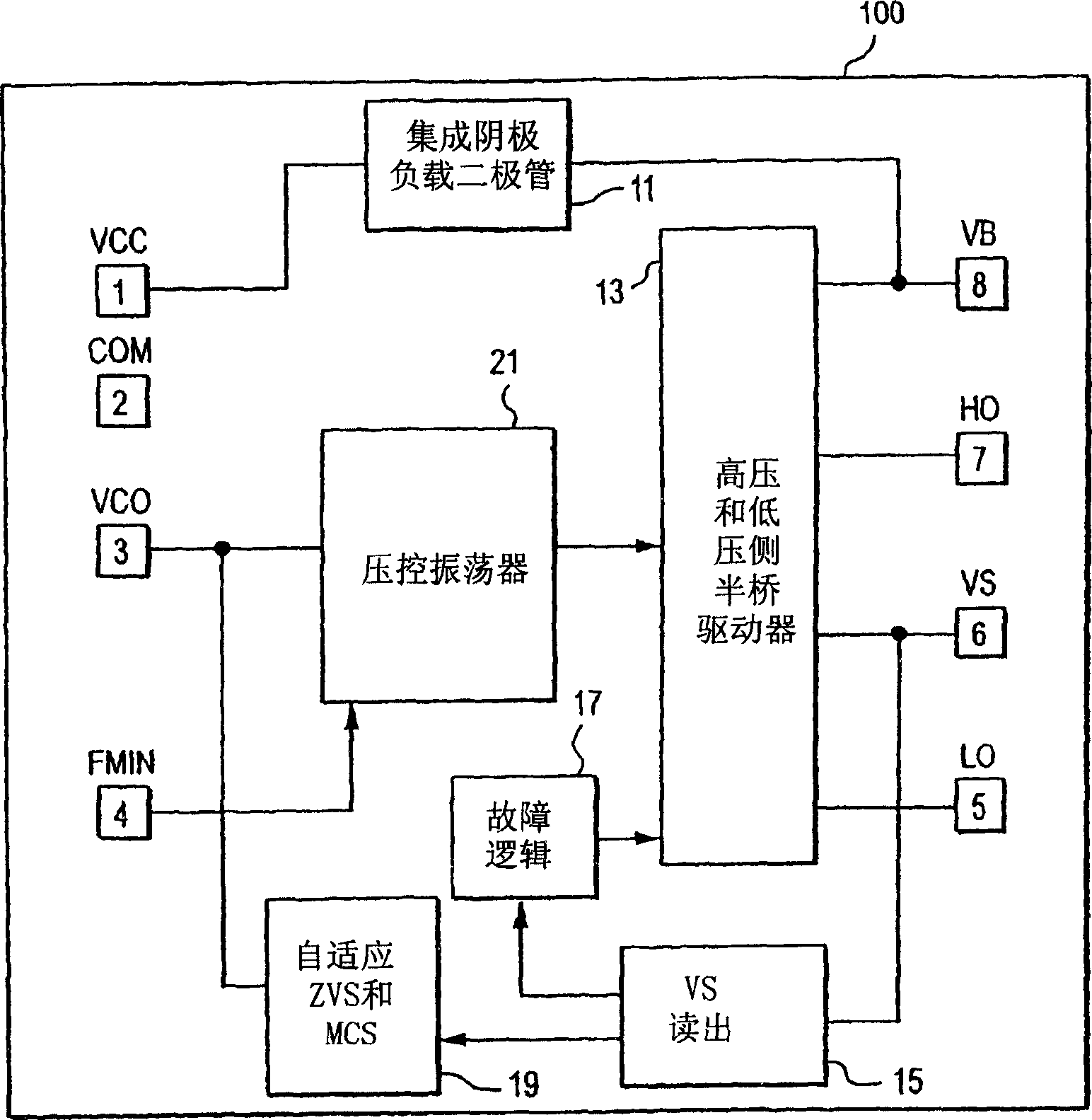
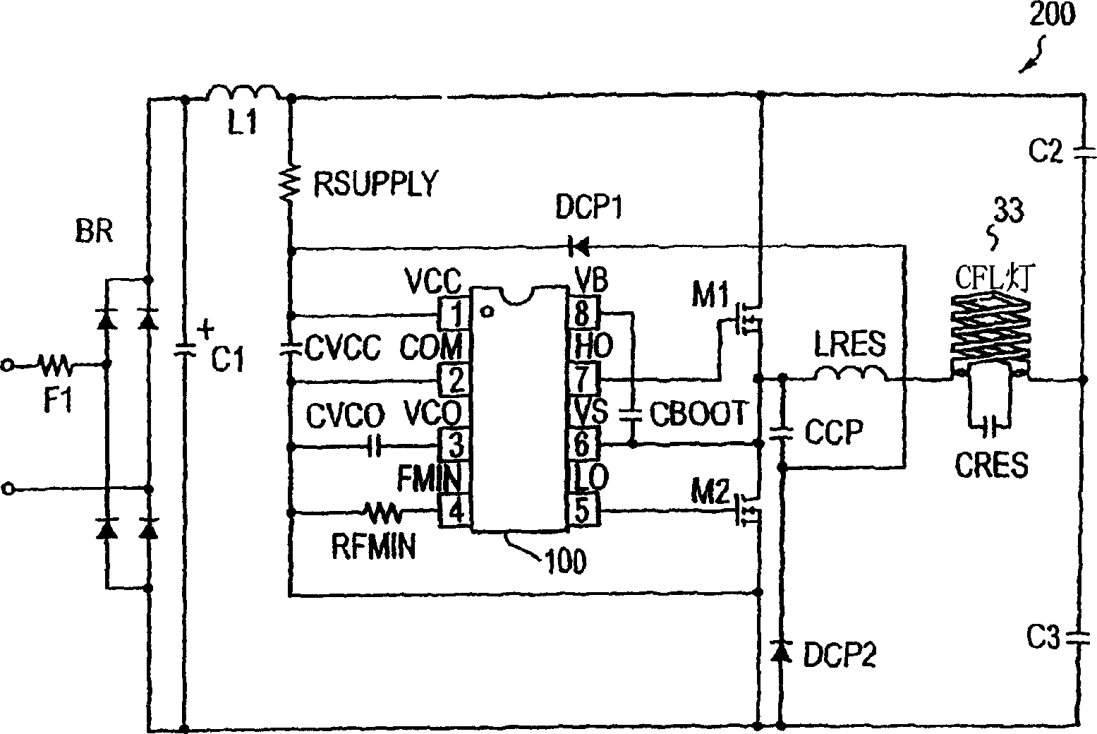
[0025] now refer to figure 1 , depicts a block diagram of the integrated control circuit 100 according to the present invention. The control circuit 100 includes labels for the pinouts of the integrated circuit or chip, represented by boxes of numbers 1-8. Label each pin number 1-8 with the terminology denoting the pin function. Therefore, pins 1 and 2 are labeled VCC and COM, respectively, to denote power and ground for the integrated control circuit 100 . Label pins 5-8 LO, VS, HO, and VB respectively. These labels refer to typical connections for half-bridge drivers. That is, pins 5 and 7 labeled LO and HO are responsible for providing gate signals to the low and high half-bridge power switches, respectively. Pins 6 and 8, labeled VS and VB, represent power to the low and high side switches, respectively. In a typical half-bridge configuration, the two half-bridge switches are connected together at the node provided by VS at pin 6, while the high-side switch is provided...
PUM
 Abstract
Description
Claims
Application Information
 - Generate Ideas
- Intellectual Property
- Life Sciences
- Materials
- Tech Scout
- Unparalleled Data Quality
- Higher Quality Content
- 60% Fewer Hallucinations
Browse by: Latest US Patents, China's latest patents, Technical Efficacy Thesaurus, Application Domain, Technology Topic, Popular Technical Reports.
© 2025 PatSnap. All rights reserved.Legal|Privacy policy|Modern Slavery Act Transparency Statement|Sitemap|About US| Contact US: help@patsnap.com


