Turbine rotor repair method

A technology of turbines and rotors, applied in turbines, mechanical equipment, engine components, etc., can solve problems such as reheat cracks, coarse grains, and deep welding depth and shape in the welded part.

Inactive Publication Date: 2005-11-02
MITSUBISHI HEAVY IND LTD
View PDF0 Cites 4 Cited by
  • Summary
  • Abstract
  • Description
  • Claims
  • Application Information

AI Technical Summary

Problems solved by technology

[0013] However, if only a welding method with a slow deposition rate such as the above-mentioned TIG welding is used, it will take a lot of time and cost, so it becomes an economic problem.
On the other hand, although there is submerged arc welding as a welding method with a fast deposition rate, due to its large welding heat, there are also cases where the welding depth of the welded part is deep and the welding heat cycle is not thorough. , the grains are easy to coarsen, and there is a risk of reheat cracks

Method used


Image

  • Turbine rotor repair method
  • Turbine rotor repair method
  • Turbine rotor repair method

Examples


Embodiment Construction

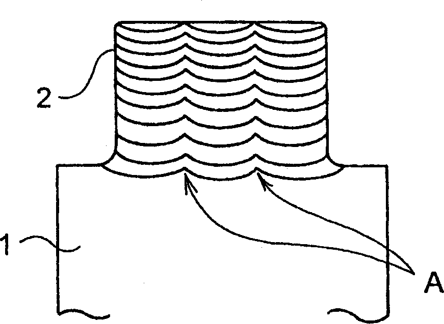
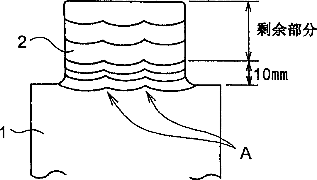
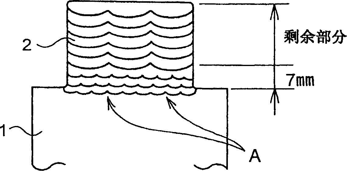
[0029] Embodiments of the present invention will be described with reference to the drawings. In the following figures, the same reference numerals are assigned to the parts that play the same role. figure 1 It is a longitudinal cross-sectional view schematically showing a repair state of the rotor by the repair method according to the first embodiment of the present invention. In order to completely fine-grain the above-mentioned welding heat-affected zone, it is important to perform overlay welding with a shallow weld bead. In order to perform welding with a high deposition rate, submerged arc welding is used in this embodiment.

[0030] Generally, it is difficult to perform shallow welding with submerged arc welding, but by using a conductive flux, it is possible to perform welding with a wide arc and a wide width and a shallow welding depth. As the conductive flux, for example, flux PFH-203 manufactured by Kobe Steel Works, Ltd. can be used.

[0031] Furthermore, weldi...


PUM

PropertyMeasurementUnit
diameteraaaaaaaaaa

Abstract

A turbine rotor repair method capable of forming a repair part by applying a deposit welding to a rotor material, the deposit welding being a thin deposit welding with a high deposition rate, wherein the repair part is formed by stacking beads by the thin deposit welding, and the thin deposit welding with the high deposition rate is performed by a submerged arc welding using a conductive flux.

Description

technical field [0001] The invention relates to a method for repairing blade grooves of a turbine rotor. Background technique [0002] Conventionally, for example, blade grooves for mounting rotor blades provided on the outer periphery of steam turbine rotors have been subjected to stress corrosion cracking due to long-term use. As one of the repair methods, there is a method of removing the cracked blade groove and restoring the blade groove by overlay welding. Figure 10 It is a vertical cross-sectional view schematically showing the repair state of the rotor by this conventional repair method. In this figure, 1 is the main body of the rotor, and 2 is the repaired part. Among them, the repair part 2 is formed by overlay welding on the rotor main body 1 from which the vane grooves have been removed. Thereafter, the blade groove (not shown) is restored by performing groove processing on the repaired portion 2 . [0003] However, the addition of vanadium to low alloy steel...

Claims


Application Information

Patent Timeline
Patent Type & Authority Applications(China)
IPC IPC(8): F01D5/12B23K9/04F01D25/00
CPCY10T29/49318Y10T29/49737B23K9/044B23K2201/001B23P6/007Y10T29/49742B23K2101/001
Inventor 福永义昭重隆司山下昌彦神吉秀典
Owner MITSUBISHI HEAVY IND LTD
Why Eureka
Try Eureka