
MEMS component vacuum fusion welding device

A vacuum and fusion welding technology, applied in welding equipment, resistance welding equipment, manufacturing tools, etc., can solve problems such as inapplicability

Inactive Publication Date: 2005-10-26
HUAZHONG UNIV OF SCI & TECH
View PDF0 Cites 3 Cited by
  • Summary
  • Abstract
  • Description
  • Claims
  • Application Information

AI Technical Summary

Problems solved by technology

Therefore, the existing fusion welding packaging device just cannot be applied

Method used


Image

  • MEMS component vacuum fusion welding device
  • MEMS component vacuum fusion welding device

Examples


Embodiment Construction

[0012] The present invention will be further described below in conjunction with drawings and embodiments.

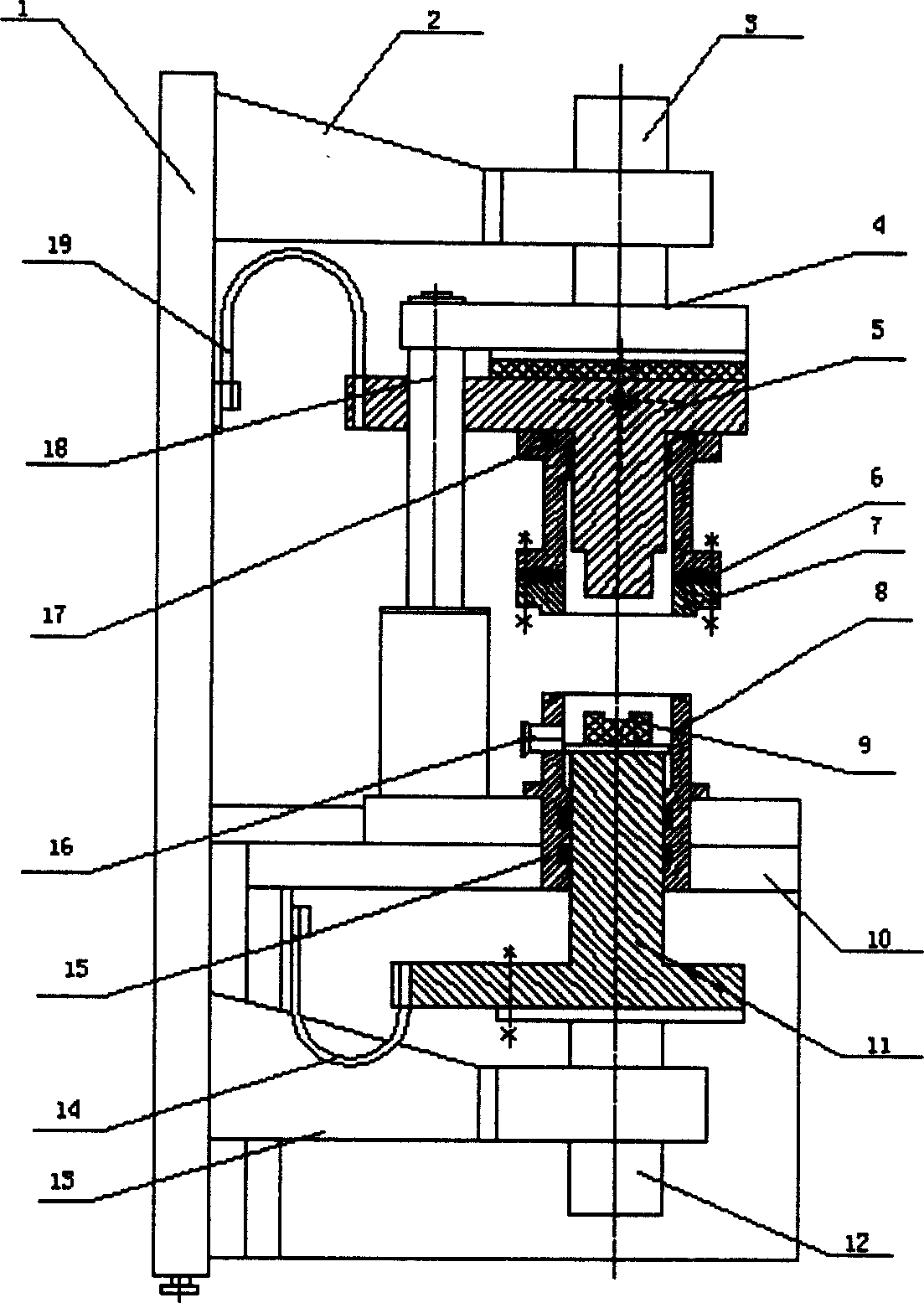
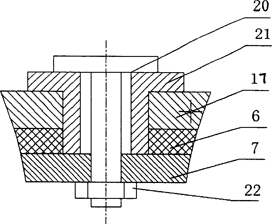
[0013] Such as figure 1 As shown, an embodiment of the present invention includes a frame 1, an upper support arm 2, an upper cylinder 3, a sliding arm 4, an upper welding arm 5, an insulating plate 6, a connecting plate 7, a lower air chamber 8, a lower support frame 10, Lower welding arm 11, lower cylinder 12, lower support arm 13, lower electrode connection belt 14, O-ring 15, vacuum interface 16, upper air chamber 17, sliding support frame 18, upper electrode connection belt 19. The upper cylinder 3 is fixed on the upper support arm 2, the upper air chamber 17, the connecting plate 7, and the insulating plate 6 are connected together by insulating bolts to form the upper working chamber, and its connection structure is as follows: figure 2 Shown, among them, connecting bolt 20, insulating sleeve 21, connecting nut 22. The lower cylinder 12 is fixed on the lower s...


PUM


Abstract

A vacuum fusion welding apparatus for the vacuum packageing of resonance device MEMS is composed of machine frame, upper supporting arm, upper sylinder, lower supporting frame with slide supporting frame linked with the slide arm driven by upper cylinder in slide mode, upper welding arm fixed to said slide arm, lower supporting arm with lower cylinder linked to lower welding arm, DC power supply, and upper and lower air chambers to be vacuumized.

Description

technical field [0001] The invention belongs to a welding packaging device, in particular to a welding packaging device of a micro-electromechanical system (MEMS) under a vacuum condition. Background technique [0002] MEMS refers to a microsystem that can be produced in batches, integrating microstructures, microsensors and microactuators, signal processing and control circuits, until interface, communication and power supply are integrated. After more than ten years of development, MEMS chips have been quite mature, but many chips have not been practically used as products. The main reason is that the packaging problem has not been solved. In fact, only packaged MEMS devices can become products and be put into use, otherwise they can only stay in the laboratory stage. At present, MEMS packaging technology obviously lags behind the research of MEMS chips, and has become a bottleneck restricting the development of MEMS. [0003] Resistance fusion welding is a method of wel...

Claims


Application Information

Patent Timeline
IPC IPC(8): B23K11/31
Inventor 甘志银汪学方关荣锋张鸿海刘胜史铁林王成刚
Owner HUAZHONG UNIV OF SCI & TECH
Learn More