Continuous casting device of non-ferrous metal drum type casting parts
A non-ferrous metal and casting technology, which is applied in the field of non-ferrous metal material forming and production, can solve the problems of difficult internal structure forming and poor casting quality, and achieve the effects of easy automatic control, good production environment and fast solidification speed.
- Summary
- Abstract
- Description
- Claims
- Application Information
AI Technical Summary
Problems solved by technology
Method used
Image

Examples
Embodiment 1
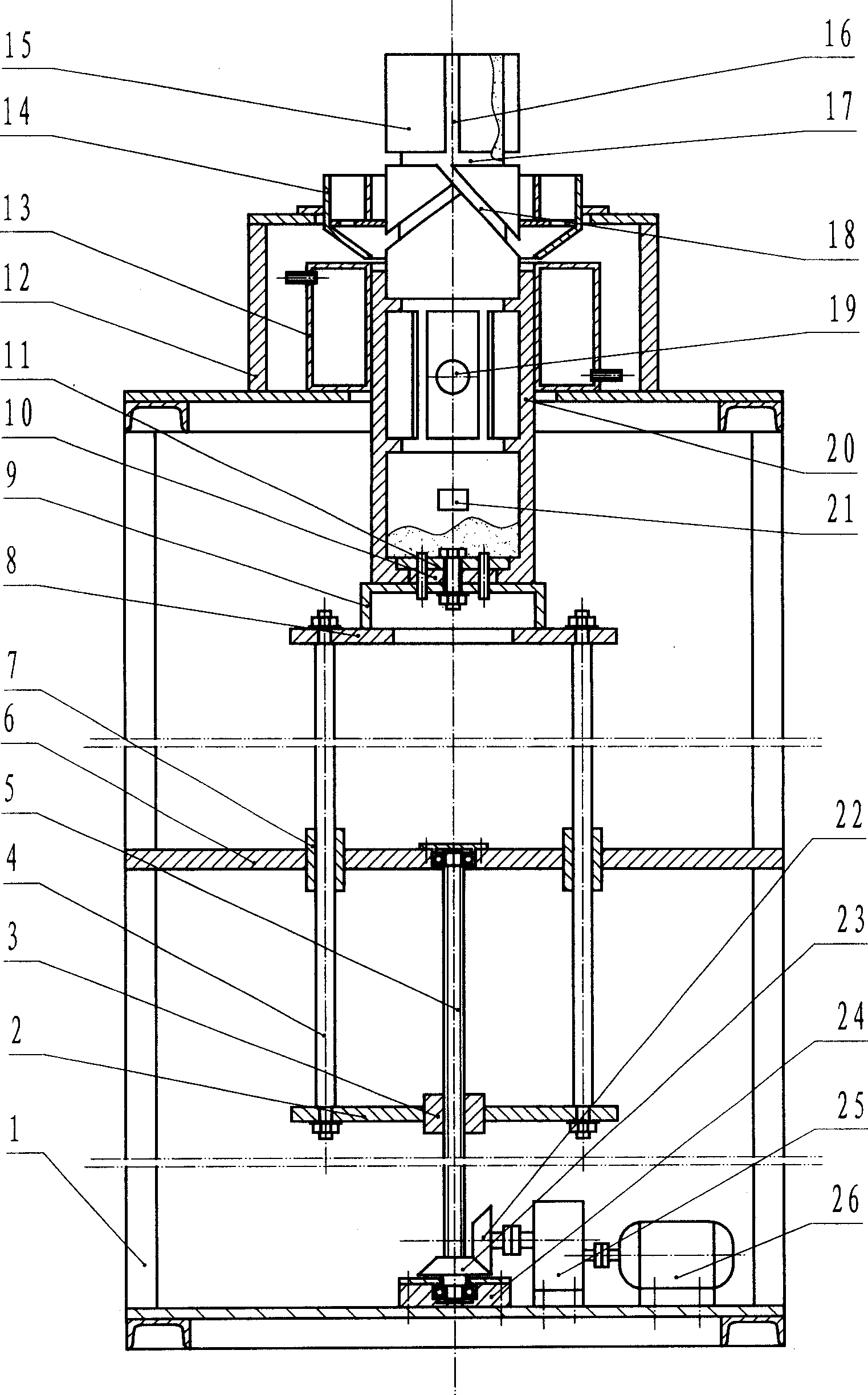
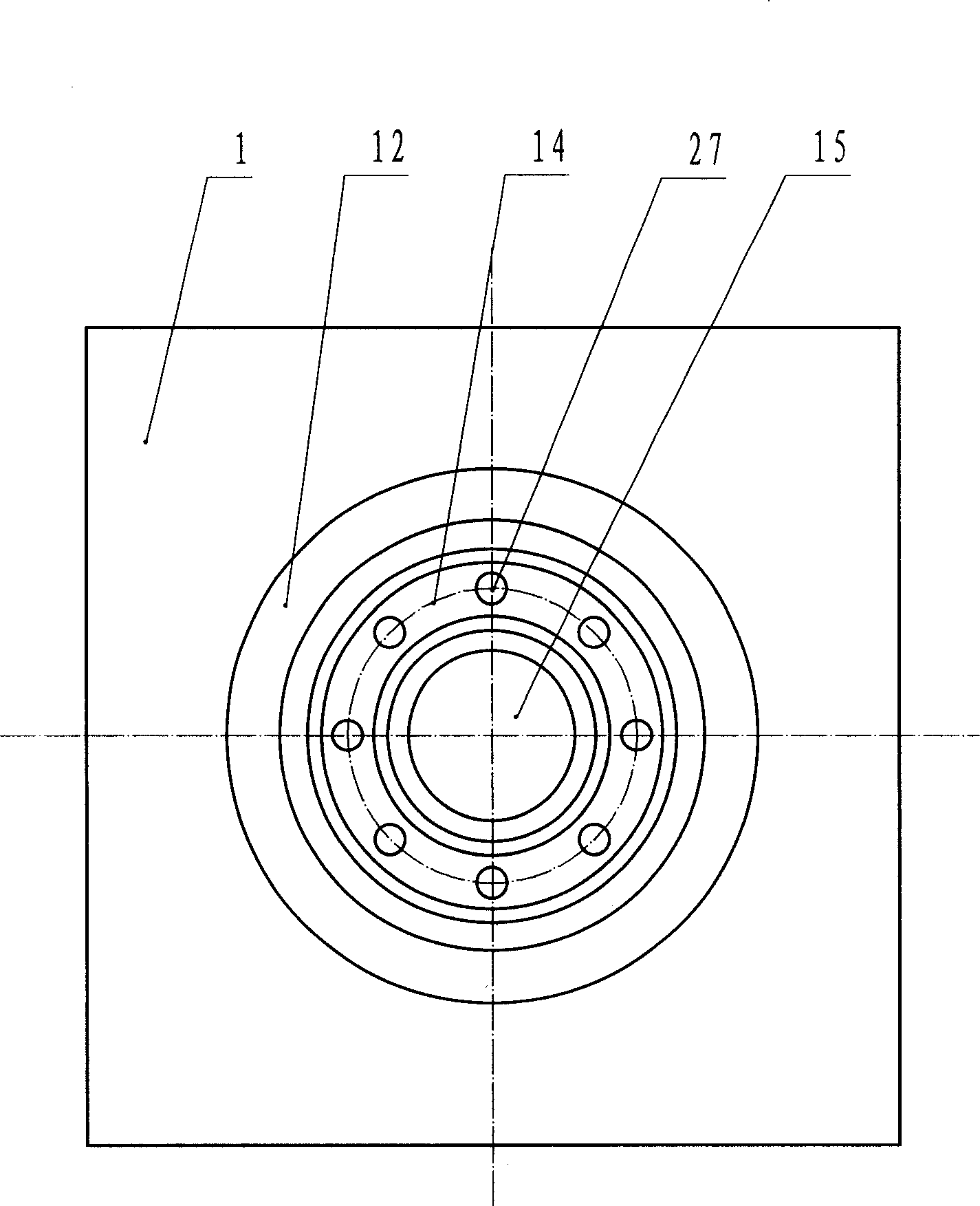
[0015] Such as figure 1 and figure 2 As shown, the present invention has a frame 1, and the frame 1 is welded with plates and profiles; a crystallizer 13 is housed on the platform at the top of the frame 1, and the crystallizer 13 is a closed water jacket structure, and at its upper and lower parts There is a water inlet and a water outlet respectively; a gate ring 14 is installed on the crystallizer 13, and the gate ring 14 is composed of an inner ring, an outer ring, an annular bottom plate, a cone and an annular support plate, and the annular bottom plate is located on the inner ring and the bottom of the outer ring, the cone is located at the bottom of the outer ring, and the annular supporting plate is located outside the outer ring, and the annular supporting plate supports the sprue ring 14 on the support 12, and the support 12 is installed on the platform on the upper part of the frame 1 Above; there are several through holes 27 on the annular bottom plate of the gat...
Embodiment 2
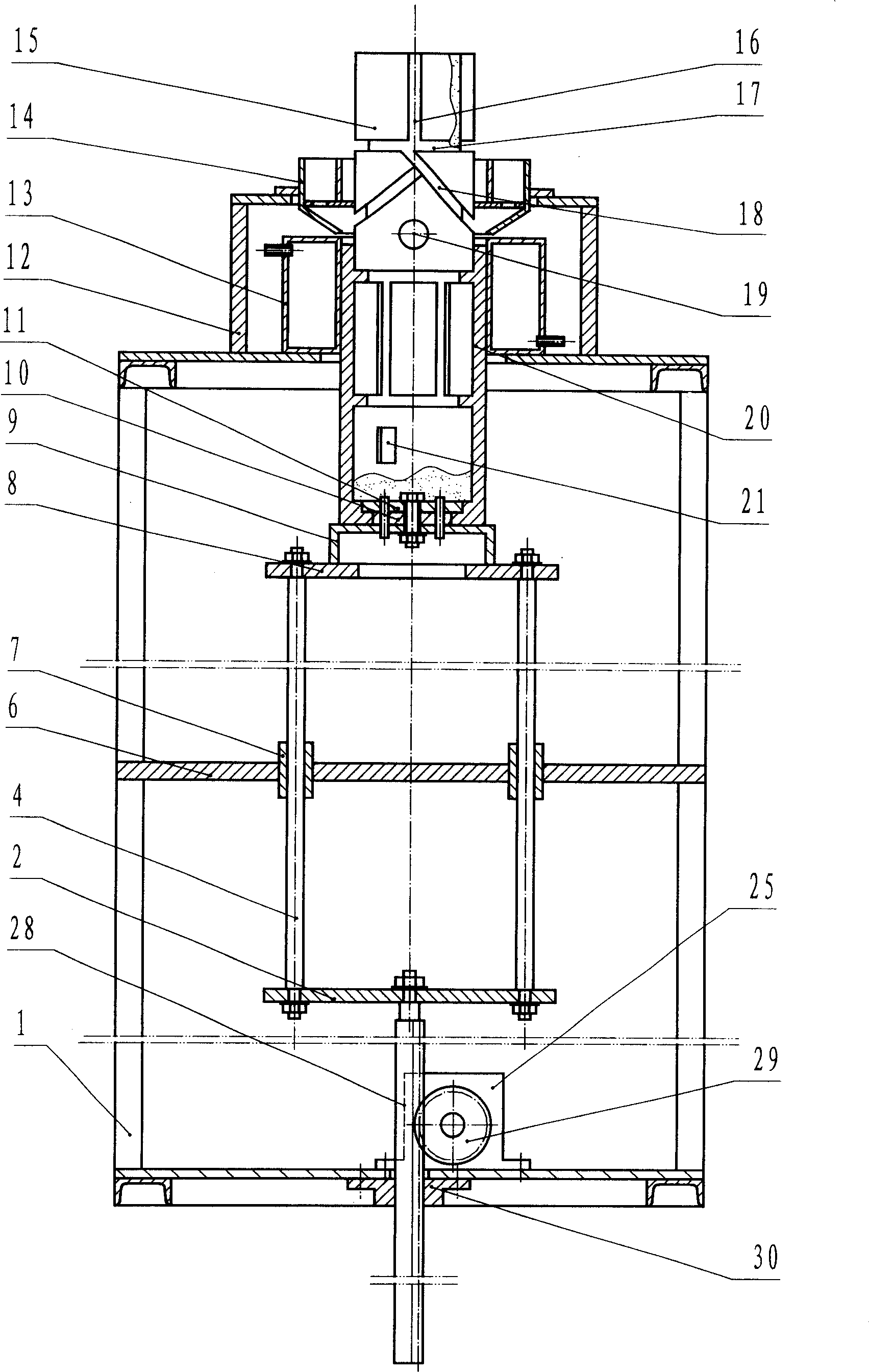
[0017] Such as image 3 As shown, its structure is as in embodiment 1, the difference is that the drive device is composed of a rack 28, a gear 29, a speed reducer 25 and a motor 26, and the upper end of the rack 28 is fixed on the connecting plate 2 of the sliding bracket , the lower end of rack 28 is installed on the base plate of frame 1 by holder 30, and gear 29 is fixed on the output shaft of speed reducer 25, and meshes with rack 28, drives sliding bracket to move up and down by rack 28.
Embodiment 3
[0019] Such as Figure 4 As shown, its structure is like embodiment 1, and the difference is that there is also a transverse strip-shaped protrusion 31 on the sand core 15, and the strip-shaped protrusion 31 surrounds the sand core 15 for a week, and can also surround the sand core 15 for half a circle, according to The internal shape of the casting 20 is required to be determined, or longitudinal and oblique strip-shaped protrusions are arranged on the sand core 15 to meet the internal shape requirements of the casting 20; the driving device is a hydraulic cylinder 32, and the upper end of the hydraulic cylinder 32 Installed on the connecting plate 2 of the sliding bracket, the lower end is installed on the bottom plate of the frame 1, and the hydraulic cylinder 32 drives the sliding bracket to move up and down.
[0020] During operation, first make corresponding sand core 15 according to the inner shape of casting 20, then sand core 15 is fixed on the traction head of tracti...
PUM
 Abstract
Description
Claims
Application Information
 - Generate Ideas
- Intellectual Property
- Life Sciences
- Materials
- Tech Scout
- Unparalleled Data Quality
- Higher Quality Content
- 60% Fewer Hallucinations
Browse by: Latest US Patents, China's latest patents, Technical Efficacy Thesaurus, Application Domain, Technology Topic, Popular Technical Reports.
© 2025 PatSnap. All rights reserved.Legal|Privacy policy|Modern Slavery Act Transparency Statement|Sitemap|About US| Contact US: help@patsnap.com