Soft-switching half-bridge inverter power supply system
An arc machining and power supply device technology, applied in positioning devices, metal machining, adjusting electrical variables, etc., can solve the problems of increased cost, complex main circuit circuit structure, complex main circuit control circuit, etc., to achieve high frequency, realize The effect of miniaturization and reduction of turn-off loss
- Summary
- Abstract
- Description
- Claims
- Application Information
AI Technical Summary
Problems solved by technology
Method used
Image

Examples
Embodiment approach 1
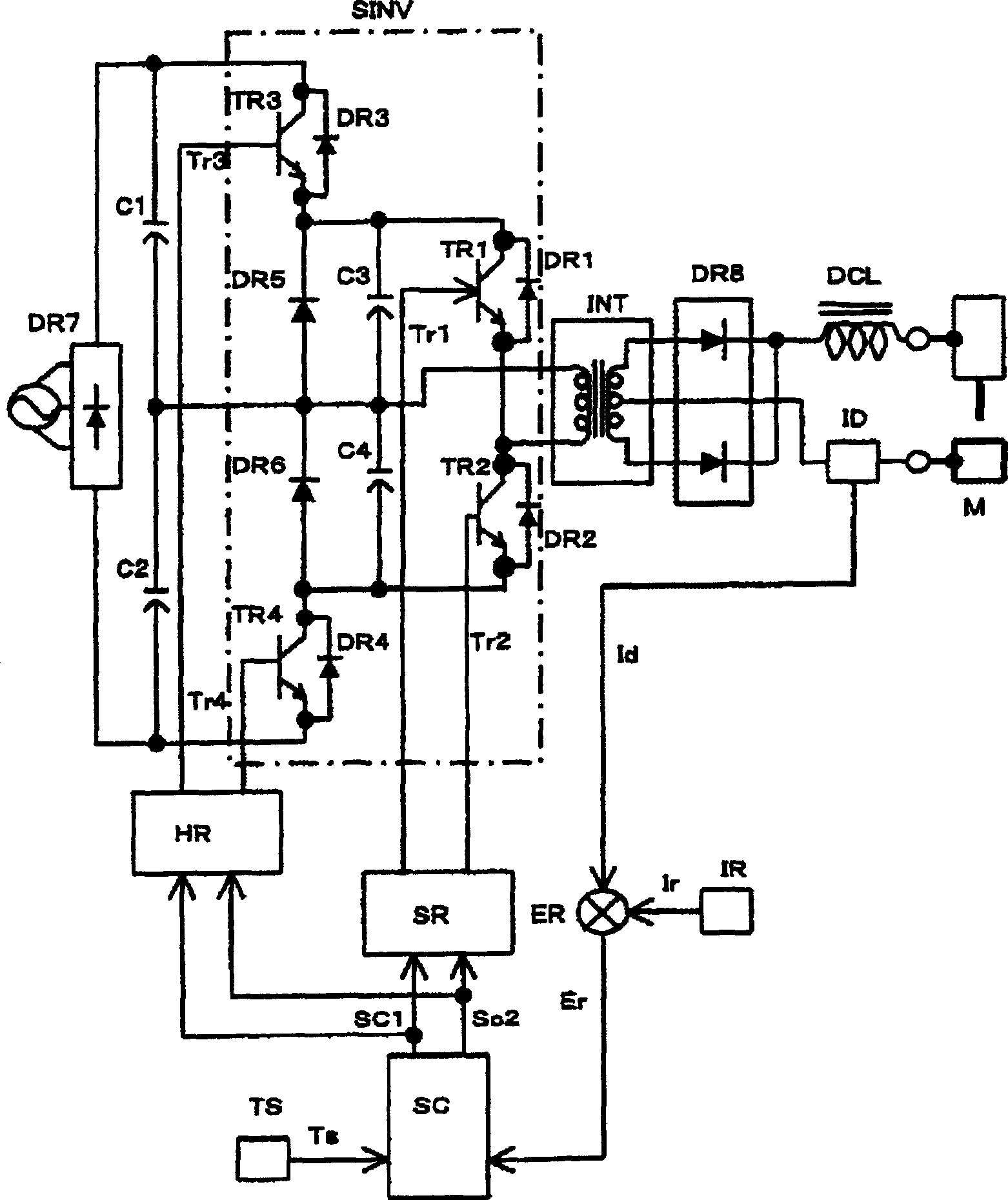
[0037] figure 1 It is an electrical connection diagram showing the power supply device for arc machining of the present invention corresponding to high voltage. exist figure 1 Here, the first smoothing capacitor C1 and the second smoothing capacitor C2 are series circuits provided in parallel between the output terminals of the primary rectification circuit DR7, and the capacitance values of the two capacitors are set to be the same. In addition, the primary rectification circuit DR7, which rectifies and converts the output of the AC commercial power supply AC into a DC voltage, corresponds to the first smoothing capacitor C1 and the second smoothing capacitor C2, which filter the DC voltage converted by the primary rectification circuit DR7. High voltage DC power circuit.
[0038] exist figure 1 The half-bridge connected inverter circuit shown in is formed by the first switching element TR1, the second switching element TR2, the first auxiliary capacitor C3, and the s...
Embodiment approach 2
[0054] Figure 4 It is an electrical connection diagram showing the power supply device for arc machining according to Embodiment 2 corresponding to high voltage. exist Figure 4 in and in figure 1 The same reference numerals in the electrical connection diagram showing the electric power supply device for arc machining according to Embodiment 1 of the present invention denote the same operation, and therefore description thereof will be omitted, and different operations will be described.
[0055] The first primary voltage detection circuit CV1 is connected to both ends of the first auxiliary capacitor C3, detects the discharge voltage of the first auxiliary capacitor C3, and outputs it as a first primary voltage detection signal Cv1. Also, the second primary voltage detection circuit CV2 is connected to both ends of the second auxiliary capacitor C4, detects the discharge voltage of the second auxiliary capacitor C4, and outputs it as a second primary voltage detection si...
Embodiment approach 3
[0061] Figure 6 It is an electrical connection diagram showing the power supply device for arc machining according to Embodiment 3 corresponding to high voltage. exist Figure 6 in, with in figure 1 The same reference numerals in the electrical connection diagram showing the electric power supply device for arc machining according to Embodiment 1 of the present invention denote the same operation, so the description will be omitted, and the different operations will be described.
[0062] The primary current detection circuit CT is connected between the contact between the first switching element TR1 and the second switching element TR2 and the primary side of the main transformer INT, detects a primary current, and outputs it as a primary current detection signal Ct.
[0063] The inverter drive circuit SRI corresponding to the primary current is composed of Figure 7 The third OR gate OR4 shown in , the fourth OR gate OR4, the conversion drive setting time limit circuit ...
PUM
 Abstract
Description
Claims
Application Information
 - R&D
- Intellectual Property
- Life Sciences
- Materials
- Tech Scout
- Unparalleled Data Quality
- Higher Quality Content
- 60% Fewer Hallucinations
Browse by: Latest US Patents, China's latest patents, Technical Efficacy Thesaurus, Application Domain, Technology Topic, Popular Technical Reports.
© 2025 PatSnap. All rights reserved.Legal|Privacy policy|Modern Slavery Act Transparency Statement|Sitemap|About US| Contact US: help@patsnap.com