Clock-locked frequency deviation detecting device

A detection device, a technology of frequency deviation, applied in the direction of automatic power control, electrical components, etc., can solve problems such as unfavorable circuit integration and chip design, increase design cost, consume resources, etc. , The effect of reducing the cost of circuit design and reducing the difficulty of circuit design

Inactive Publication Date: 2010-04-28
HUAWEI TECH CO LTD
View PDF3 Cites 0 Cited by
  • Summary
  • Abstract
  • Description
  • Claims
  • Application Information

AI Technical Summary

Problems solved by technology

[0012] This counting scheme needs to add an analog circuit, which increases the design cost, and is not conducive to the integration of the circuit and the design of the chip.
At the same time, the accuracy of circuit devices is very high. According to practical experience, when the device accuracy is not high enough, it will lead to detection errors, and the frequency difference will be reported as out of lock within the allowable range.
In addition, the circuit is susceptible to interference. Due to the use of the integral circuit, the integral output is very sensitive to the jitter of the integral input. For example, when the frequency difference threshold is near, the noise is easy to jitter the integral output, which makes the lock-out alarm appear and disappear continuously.
[0013] In practical application, the above-mentioned solution has the following problems: first, it needs to use analog circuits or a large number of logic resources for lock detection, which not only consumes resources, but also requires high components, which leads to increased costs; second, the use of analog circuits is not conducive to circuit integration. and chip design; the reliability of the third circuit is not high, making the detection error-prone, so the design is relatively difficult
[0014] The main reason for this situation is that the first technical solution is directly implemented by a digital counter, which directly counts and compares clock signals without any other processing, so that the counter needs to use a large number of logic resources, and the performance of multi-bit comparison is reduced; The second technical solution is realized by analog circuit, which has the disadvantage that it is not easy to integrate

Method used


Image

  • Clock-locked frequency deviation detecting device
  • Clock-locked frequency deviation detecting device
  • Clock-locked frequency deviation detecting device

Examples


Embodiment Construction

[0034] In order to make the object, technical solution and advantages of the present invention clearer, the present invention will be further described in detail below in conjunction with the accompanying drawings.
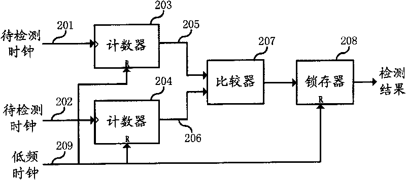
[0035]The basic idea of ​​the present invention is to accumulate and judge the phase difference between the reference clock signal and the output clock signal, which is realized by a digital logic circuit. Specifically, the present invention first determines a detection range according to a low-frequency clock signal, uses two low-bit counters to carry out cyclic counting to the reference clock signal and the output clock signal in this detection range, and counts the counts of the two counters in the counting process Values ​​are compared asynchronously, and the detection of loss of lock and frequency difference can be realized by setting the threshold value. Different from the prior art solution, the present invention adopts the comparison of low-digit counters ...


PUM


Abstract

The invention relates to a clock lock device used in electric device and discloses a detector device of clock lock and frequency deviance. The device comprises a first counter and a second counter that has the same number of bits that are separately used to cycle count the clock signal of the two ways of detecting circuit; a comparer that is used to asynchronous compare the value of the first counter and the second counter, output the comparing result according to the threshold value a flip-latch that is used to output detecting result according to the comparing sesult and a low frequency clock signal used to identify detecting range and initialize the first counter, the second counter and flip-latch.

Description

technical field [0001] The invention relates to a clock locking device in electronic equipment, in particular to a detection device for detecting whether an output clock is locked to a reference clock in electronic equipment and chip design. Background technique [0002] The clock is a key component of any sequential digital circuit, especially for communication equipment, automatic control systems, and computer hardware with high timing and frequency requirements, it is a key factor that affects communication quality, control accuracy, and computing efficiency. [0003] The quality of the clock directly affects the performance of a single board or even the entire system. A clock generating device can be used as a local clock source of an ordinary digital circuit, and a synchronous clock source circuit is generally realized by a dedicated phase-locked loop (Phase Lock Loop, "PLL") device. The working principle of the phase-locked loop is to identify the phase of the frequen...

Claims


Application Information

Patent Timeline
IPC IPC(8): H03L7/00H03L7/06
Inventor 乔永强
Owner HUAWEI TECH CO LTD
Why Eureka
Try Eureka