
Backlight module

A backlight module and lamp technology, applied in optics, nonlinear optics, instruments, etc., can solve the problem of low heat dissipation efficiency of the backlight module, and achieve the effect of improving the internal heat dissipation effect and high heat conduction speed.

Inactive Publication Date: 2005-07-20
HONG FU JIN PRECISION IND (SHENZHEN) CO LTD +1
View PDF1 Cites 8 Cited by
  • Summary
  • Abstract
  • Description
  • Claims
  • Application Information

AI Technical Summary

Problems solved by technology

[0006] In order to overcome the problem of low heat dissipation efficiency of backlight modules in the prior art, the present invention provides a backlight module with high heat dissipation efficiency

Method used


Image

  • Backlight module
  • Backlight module
  • Backlight module

Examples


Embodiment Construction

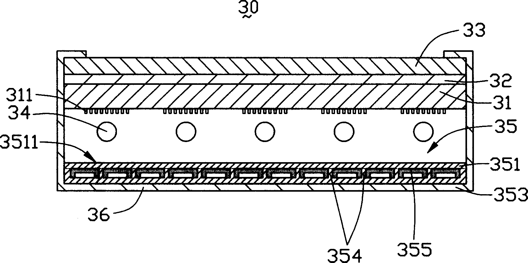
[0014] see figure 2 , is the first embodiment of the backlight module of the present invention. The backlight module 30 includes a plurality of lamp tubes 34 , a diffusion plate 31 , a light enhancement sheet 32 ​​, a diffusion sheet 33 , a heat dissipation hollow reflector 35 and an outer frame 36 .

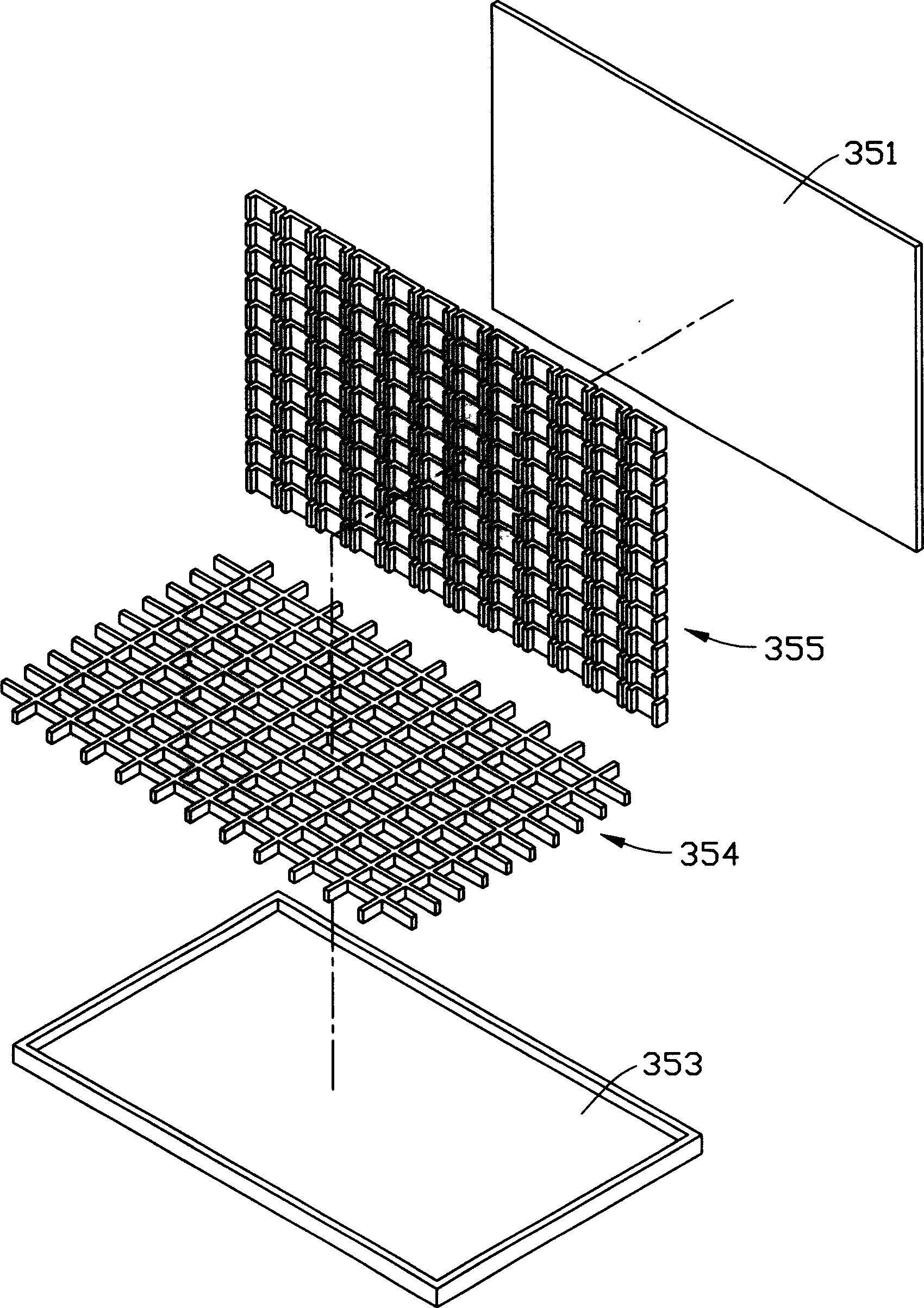
[0015] The diffuser plate 31, the brightness enhancement sheet 32 ​​and the diffuser sheet 33 are sequentially arranged above the lamp tube 34; the heat dissipation hollow reflector 35 is arranged below the lamp tube 34, and its surface facing the lamp tube 34 is a reflective surface 3511. The reflective surface 3511 is used to reflect the light generated by the lamp tube 34 to the diffuser plate 31; the outer frame 36 holds the lamp tube 34, the diffuser plate 31, the brightness enhancement sheet 32, the diffuser sheet 33 and the heat dissipation hollow reflector plate 35 inside. .

[0016] The lamp tube 34 is a cold-cathode fluorescent lamp tube, and the diffuser plate 31 i...


PUM


Abstract

This invention discloses a kind of apheliotropic module group including several lamp tubes, a diffusing board and a inside-vacant cooling reflecting board. The diffusing board is equipped above the lamp tubes, while the inside-vacant cooling reflecting board is equipped below the lamp tubes which is board-shape thermic tube structure and the surface just opposite the lamp tubes is the reflecting plane.

Description

【Technical field】 [0001] The invention relates to a backlight module, in particular to a backlight module with a cooling device. 【Background technique】 [0002] Due to the advantages of light weight, thin thickness, and low power consumption, liquid crystal displays are widely used in modern information equipment such as notebook computers, mobile phones, and personal digital assistants. Because the liquid crystal itself does not have light-emitting properties, it is necessary to provide a backlight module for it to realize the display function. [0003] Backlight modules can generally be divided into two types: edge-lit and direct-lit. For small and medium-sized liquid crystal displays, the edge-lit backlight module has the advantages of lightness, thinness, and low power consumption. However, with the development of science and technology, the demand for large-size liquid crystal displays is increasing day by day, and the performance of large-size edge-lit backlight modu...

Claims


Application Information

Patent Timeline
Patent Type & Authority Applications(China)
IPC IPC(8): G02F1/1335G02F1/13357
Inventor 简士哲
Owner HONG FU JIN PRECISION IND (SHENZHEN) CO LTD
Learn More