Radio communication device, receiver device, and reception manner selecting method
A technology of wireless communication equipment and solutions, applied in wireless communication, shaping network in transmitter/receiver, communication between multiple stations, etc., can solve the problems of reduced throughput, high error rate of received data, etc.
- Summary
- Abstract
- Description
- Claims
- Application Information
AI Technical Summary
Problems solved by technology
Method used
Image
Examples
Embodiment 1
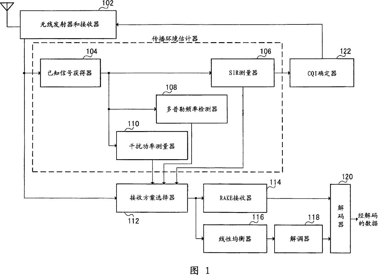
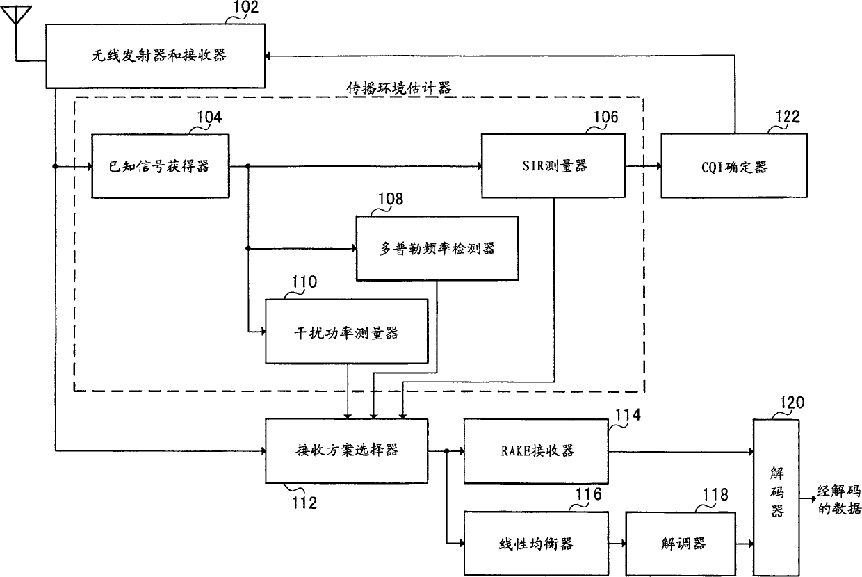
[0034] FIG. 1 is a block diagram showing the configuration of a mobile station apparatus according to Embodiment 1 of the present invention. The mobile station apparatus shown in FIG. 1 has a wireless transmitter and receiver 102, a known signal obtainer 104, an SIR measurer 106, a Doppler frequency detector 108, an interference power measurer 110, a reception scheme selector 112, RAKE receiver 114 , linear equalizer 116 , demodulator 118 , decoder 120 and CQI determiner 122 .
[0035] The wireless transmitter and receiver 102 transmits and receives signals through an antenna, and performs predetermined wireless processing (including down conversion, A / D conversion, D / A conversion, and up conversion). The known signal obtainer 104 obtains known signals from the signals received by the wireless transmitter and receiver 102 .
[0036] The SIR measurer 106 measures the SIR of a known signal. SIR represents the ratio of signal power to interference power. From the SIR, a CQI to...
Embodiment 2
[0050] Embodiment 2 of the present invention is characterized in that the mobile station apparatus selects a reception scheme according to the propagation environment and at the same time transmits to the base station apparatus a CQI class that will cause a high transmission rate MCS to be selected.
[0051] Fig. 3 is a block diagram illustrating the configuration of a mobile station device according to this embodiment. The same parts in the mobile station apparatus shown in this figure as in the mobile station apparatus shown in FIG. 1 will be assigned the same reference numerals and no further explanation will be given.
[0052] The mobile station apparatus shown in FIG. 3 has a wireless transmitter and receiver 102, a known signal obtainer 104, an SIR measurer 106, a Doppler frequency detector 108, an interference power measurer 110, a reception scheme selector 112, RAKE receiver 114, linear equalizer 116, demodulator 118, decoder 120, and CQI determiner 122a.
[0053] The...
Embodiment 3
[0061] Embodiment 3 of the present invention is characterized in that, depending on the propagation environment, the base station device will select a reception scheme and report the selected reception scheme to the mobile station device.
[0062] Fig. 6 is a block diagram showing the configuration of a base station device according to this embodiment. The base station equipment as shown in accompanying drawing 6 has wireless transmitter and receiver 202, Doppler frequency detector 204, CQI extractor 206, receiving scheme selector 208, report signal generator 210, MCS selector 212, adaptive Encoder 214 , adaptive modulator 216 , and multiplexer 218 .
[0063] The wireless transmitter and receiver 202 transmits and receives signals through an antenna, and performs predetermined wireless processing (including down conversion, A / D conversion, D / A conversion, and up conversion). The Doppler frequency detector 204 detects the Doppler frequency from the received signal and measures...
PUM
 Abstract
Description
Claims
Application Information
 - R&D
- Intellectual Property
- Life Sciences
- Materials
- Tech Scout
- Unparalleled Data Quality
- Higher Quality Content
- 60% Fewer Hallucinations
Browse by: Latest US Patents, China's latest patents, Technical Efficacy Thesaurus, Application Domain, Technology Topic, Popular Technical Reports.
© 2025 PatSnap. All rights reserved.Legal|Privacy policy|Modern Slavery Act Transparency Statement|Sitemap|About US| Contact US: help@patsnap.com


