Liquid crystal display device

一种液晶显示装置、薄膜晶体管的技术,应用在晶体管、光学、仪器等方向,能够解决光泄漏、对比度下降、黑亮度增加等问题

Active Publication Date: 2005-07-13
NEC LCD TECH CORP
View PDF4 Cites 14 Cited by
  • Summary
  • Abstract
  • Description
  • Claims
  • Application Information

AI Technical Summary

Problems solved by technology

In an IPS system generally employing a black drive, the disturbance of the initial orientation causes light leakage near the step of the third insulating film at the time of black display
Therefore, black luminance increases, resulting in a decrease in contrast

Method used


Image

  • Liquid crystal display device
  • Liquid crystal display device
  • Liquid crystal display device

Examples


Embodiment Construction

[0040] Preferred embodiments of the present invention will be described below with reference to the accompanying drawings.

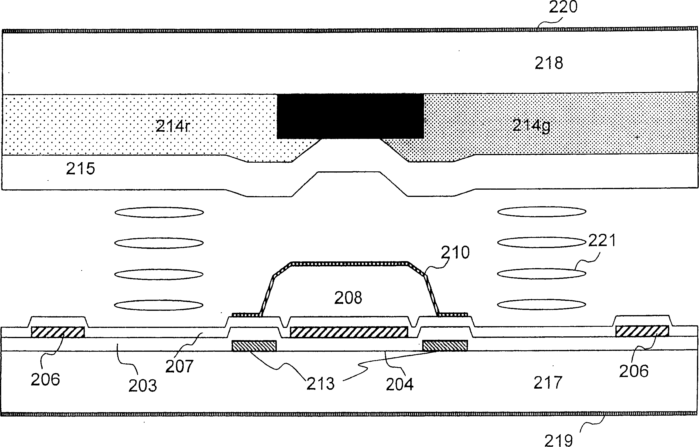
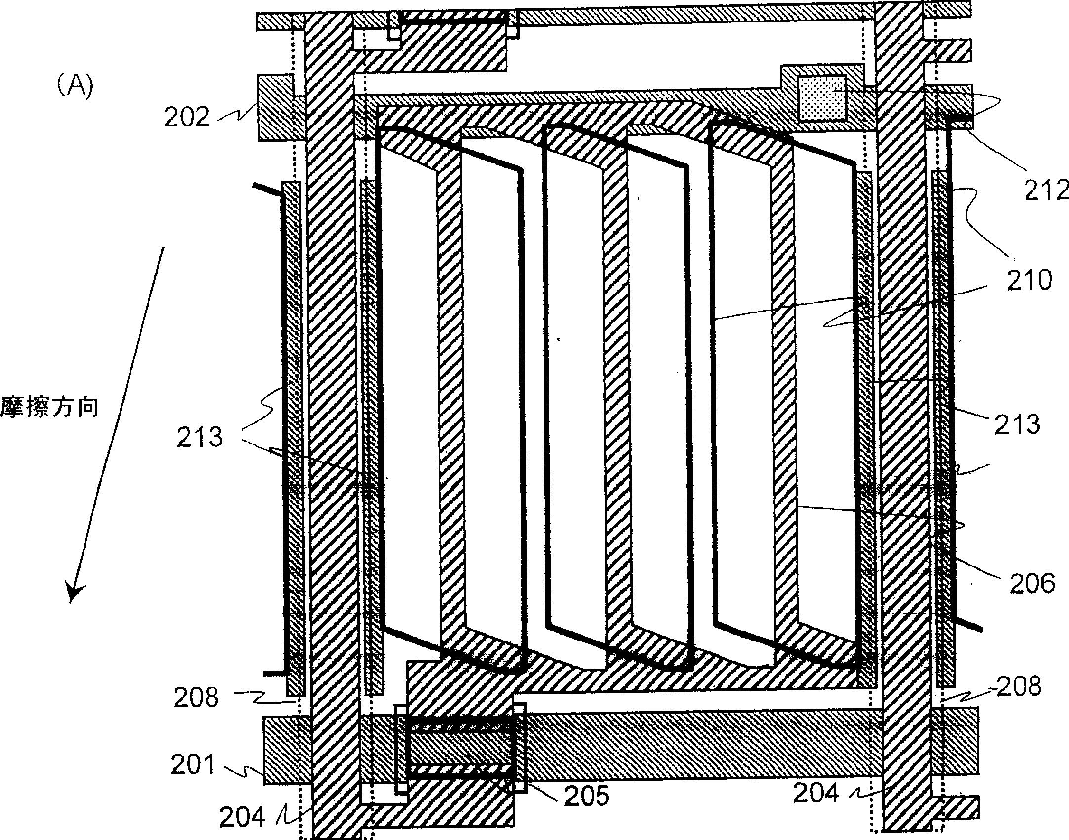
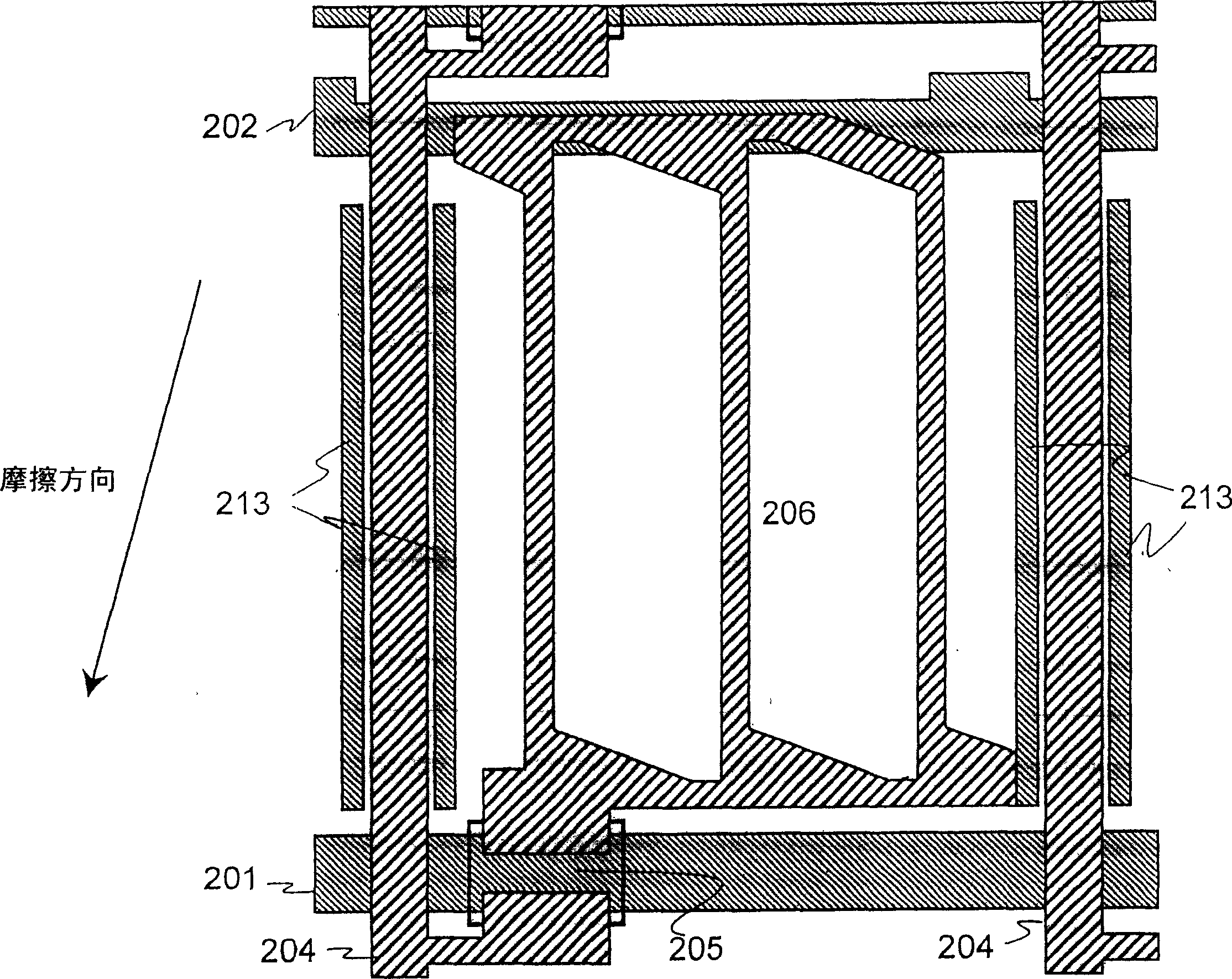
[0041] figure 1 , 2A and 2B show a first embodiment of the liquid crystal display device according to the present invention. Figure 2A is a plan view of one pixel of the first embodiment of the liquid crystal display device according to the present invention. Figure 2B It is a plan view of this embodiment omitting the common electrode and the bank-shaped third insulating film formed on the video signal line. figure 1 is a cross-sectional view of the surrounding area of ​​the video signal line shown in FIG. 2 .

[0042] On the first substrate, scanning signal lines 201 , common signal lines 202 extending parallel to the scanning signal lines, and light-shielding electrodes 213 provided adjacent to opposite sides of video signal lines to be described later are formed. These lines and electrodes are formed from the first metal layer. The light-shie...


PUM

PropertyMeasurementUnit
lengthaaaaaaaaaa

Abstract

The present invention discloses an active matrix type liquid crystal display device in a transverse electric field system, in which a high aperture factor can be ensured even at a narrow pitch, and a high contrast ratio and reduced vertical impact can also be ensured. In a liquid crystal display device, a substantially bank-shaped insulating film (208) forms a video signal line (204) and is covered by a common electrode (210), and a light-shielding electrode (213) is formed on the common electrode (210) from the video signal line (210). 204) below the part where the edge extends. With this arrangement, a liquid crystal display device is realized that shields light from one side of the stepped portion and ensures a high aperture coefficient and high contrast.

Description

technical field [0001] This application claims priority from Japanese Patent Application No. 2004-002782 filed on January 8, 2003, the contents of which are hereby incorporated by reference. [0002] The invention relates to a liquid crystal display device, in particular to an active matrix liquid crystal display device in a transverse electric field system capable of obtaining high aperture coefficient and high contrast. Background technique [0003] The N (twisted nematic) system widely used so far ensures high contrast. However, on the downside, the molecular axes of the liquid crystal are lifted by the vertical electric field. This implies a significant field of view angle dependence. Recently, the demand for a system for a large-sized display such as a television is increasing, and an IPS (In-Plane Switching) system has been widely adopted. In an IPS system, for display, liquid crystal molecule axes are rotated by a transverse electric field in a plane parallel to th...

Claims


Application Information

Patent Timeline
Patent Type & Authority Applications(China)
IPC IPC(8): G02F1/1333G02F1/1343G02F1/136G02F1/1362G02F1/1368G11B3/58H01L29/786
CPCG02F1/134363G02F1/136209G02F1/136218A47J41/0083A47J43/07
Inventor 今野隆之西田真一冈本守
Owner NEC LCD TECH CORP
Why Eureka
Try Eureka