Modular service unit

一种服务装置、辅助服务的技术,应用在照明装置、照明装置、固定照明装置等方向,能够解决不能应用、不能装在、有损房间外观或美观等问题

Inactive Publication Date: 2005-05-04
YANEK
View PDF6 Cites 2 Cited by
  • Summary
  • Abstract
  • Description
  • Claims
  • Application Information

AI Technical Summary

Problems solved by technology

The disadvantage of the second type of service structure is that not only is it time-consuming and expensive to install, but it also detracts from the overall appearance or aesthetics of the room in which it is installed
Because of its complex structure, the formed part is only designed as a combined lighting and ventilation unit and is therefore not suitable for installing other services instead of ventilation units
[0008] Another disadvantage of the structure of UK patent 1509259 is that it cannot be applied in existing suspended ceilings with a grid of longitudinal and transverse T-profiles
[0009] Reference may also be made to other prior art combining additional services with lighting fixtures, and to GB864894, Japanese Patent Publication 04-188998, DE3643075, US5263290 and US6443592, all of which suffer from the same disadvantages as GB1509259, namely, complex structures , cannot be installed on the above existing suspended ceiling

Method used


Image

  • Modular service unit
  • Modular service unit
  • Modular service unit

Examples


Embodiment Construction

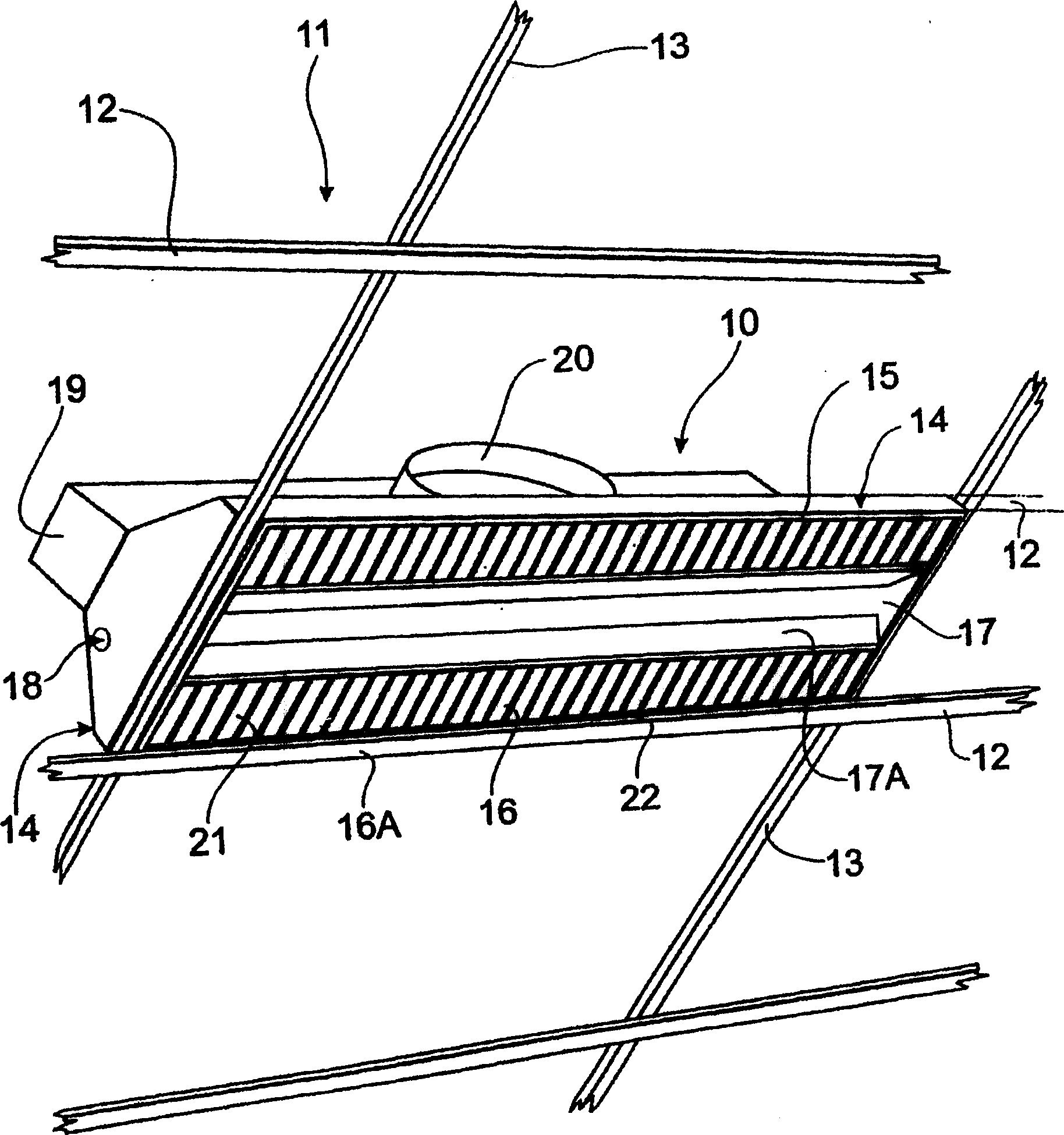
[0032] exist figure 1 Here, the modular service unit 10 is mounted on a false or suspended ceiling 11 comprising a grid or network of support elements in the form of longitudinal support elements such as T-profiles 12 and transverse support elements such as T-profiles 13. The modular service apparatus 10 includes a pair of fluorescent lamp assemblies or troffers 14 having a housing 15 , a light diffuser 16 , and a space 17 between the diffusers 16 . Each housing 15 illustrated is trough-shaped, more preferably having an inverted U-shape, with an open bottom 16A occupied by a diffuser 16 . However, it should be appreciated that each troffer housing may be C-shaped or V-shaped in cross-section. There is also a blower chamber 19 of rectangular cross-section communicating with the space 17 in which the air diffuser 17A is installed. The space 17 corresponds to the open bottom of the blower chamber 19 . A typical connection system, such as an end plate 19, is also shown. In the...


PUM


Abstract

Modular service unit (10A) comprising a pair of elongate light fittings EACH comprising a reflector housing (14) having one or more light tubes (24). Either a bridging plate, or an intermediate housing (26), is releasably attached to or supported by adjacent longitudinal side edges (34) of each reflector housing (14), and forms a structural part of an auxiliary service facility. The auxiliary service facility can include, for example, air conditioning ducts or diffusers (17A), fire alarm detectors, fire sprinklers with flexible pipe connections, speakers, security sensors, and secondary light fittings. A plurality of modular service units may be incorporated in a suspended ceiling.

Description

technical field [0001] The present invention relates to modular service units incorporated or installed in suspended or false ceilings. Background technique [0002] Hitherto, suspended ceilings have been built on the basis that support elements or a grid of support elements, usually with a T-shaped cross-section, are mounted on the roof structure between the side walls of the building space, and subsequently ceiling tiles are mounted on the support elements tiles or ceiling tiles for a beautiful look. In the space between the bracket elements and the top wall or brackets of the house there are air-conditioning ducts mounted to supply air chambers from outlets or grids including air diffusers located in the ceiling tiles or ceiling tiles to The conditioned air is exhausted from the room. Fluorescent light fixtures or troffers are also placed at intervals in the suspended ceiling, along with other services such as fire alarm detectors, fire sprinklers, safety equipment, lou...

Claims


Application Information

Patent Timeline
Patent Type & Authority Applications(China)
IPC IPC(8): E04B9/00F21S4/00F21S8/02F21S8/04F21VF21V21/04F21V29/02F21V33/00F21Y103/00F24FF24F13/072F24F13/078
CPCF21V33/0076F24F13/078F24F13/072F21V29/02F21V33/0064F21V33/0056F21V33/0092F21V29/83E04B9/02F21V33/00E04B9/00
Inventor 肯尼思·威廉·麦卡锡
Owner YANEK
Why Eureka
Try Eureka