
Magnetic suspension planar electric machine

A planar motor and magnetic levitation technology, which is applied in the direction of electrical components, magnetic attraction or thrust holding devices, etc., can solve the problems of high precision of the support plane, higher system order, wear and tear of moving parts, etc.

Inactive Publication Date: 2005-03-23
XI AN JIAOTONG UNIV
View PDF0 Cites 13 Cited by
  • Summary
  • Abstract
  • Description
  • Claims
  • Application Information

AI Technical Summary

Problems solved by technology

Mechanical friction not only increases the frictional resistance of the mover, wears out the moving parts, generates mechanical vibration and noise, increases the order of the system, reduces robustness and servo performance, but also limits the motion accuracy of the platform
In addition, its motion accuracy is limited by the support plane, which requires high precision of the support plane, which affects the dynamic response speed of the system and increases the manufacturing cost of the platform.
In addition, the complex control structure and calibration detection are also one of the factors that limit it
Therefore, the structure of the traditional processing platform makes its positioning and motion accuracy unable to meet the requirements of ultra-precision positioning and processing

Method used


Image

  • Magnetic suspension planar electric machine
  • Magnetic suspension planar electric machine
  • Magnetic suspension planar electric machine

Examples


Embodiment Construction

[0010] The structural principle and working principle of the present invention will be further described in detail below in conjunction with the accompanying drawings.

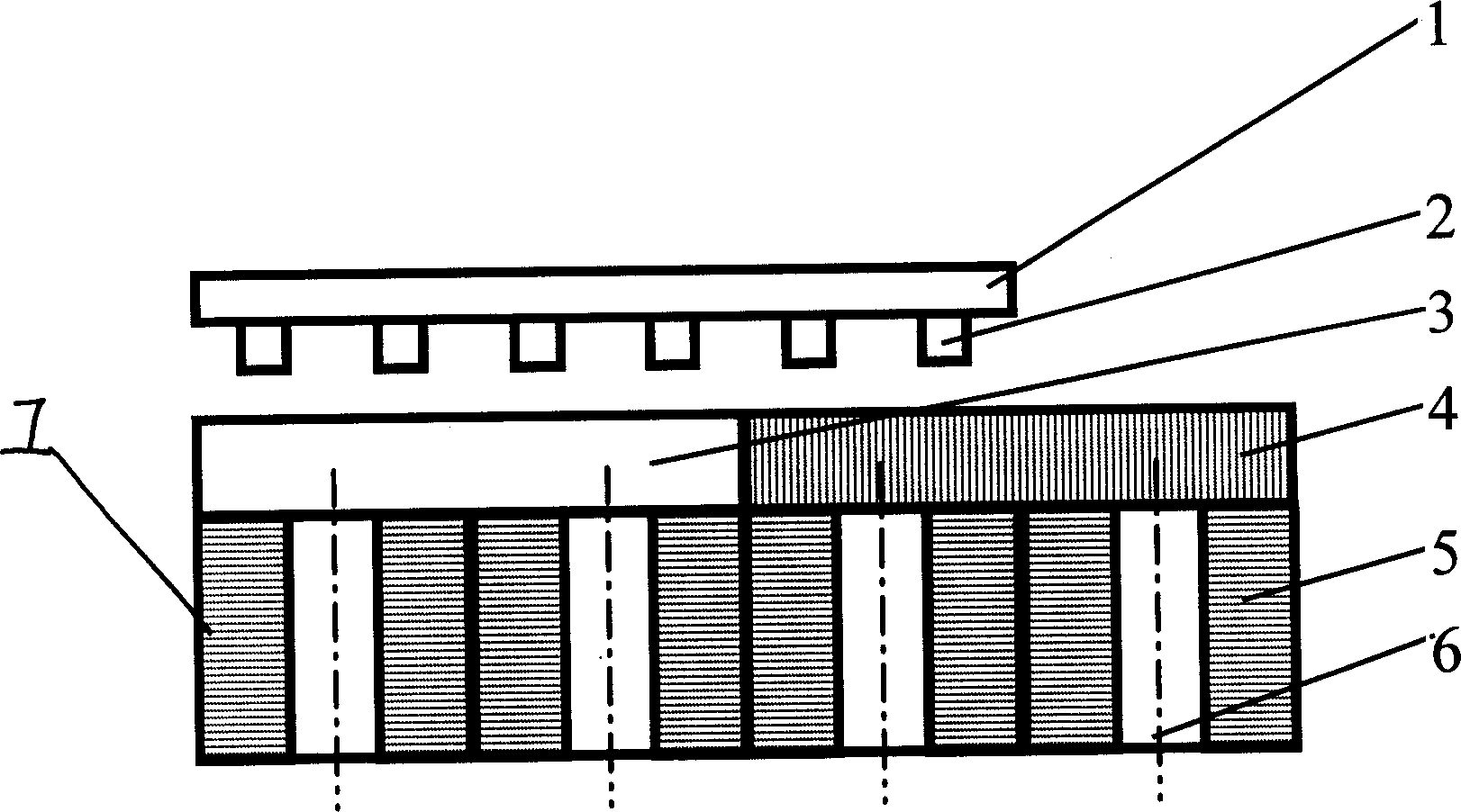
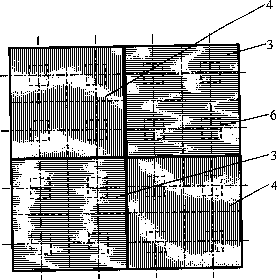
[0011] see figure 1 , the present invention includes a stator platform 7 and a mover platform 1 made of an aluminum plate with a flat and smooth upper surface that can be suspended on the stator platform 7. Several permanent magnets 2 are uniformly arranged on the lower surface of the mover platform 1, and the stator The platform 7 includes levitation coils 5 and thrust coils, and several groups of levitation coils 5 are arranged on the levitation coil frame 6 in the form of an array, and the thrust coils include the X-direction thrust coil 3 and the Y-direction thrust coil arranged on the upper surface of the levitation coil frame 6 4.

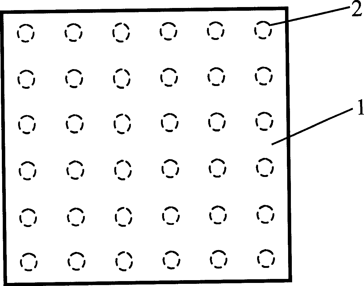
[0012] see figure 2 , The lower surface of the mover platform 1 of the present invention is evenly provided with thirty-six pieces of rare earth NdFeB permanent magnets 2 ...


PUM


Abstract

A magnetic suspension linear motor includes the stator platform, rotor platform which can suspend over the stator platform and some permanent magnets set on the lower surface of the rotor platform. The stator platform includes the suspending coils and thrust coils. Some suspending coils are set on the suspending coils frame in the form of array. The thrust coils include the thrust coils along the X and the thrust coils along the Y, which are set on the upper surface of the suspending coils frame, are parallel to the surface of the rotor platform and are normal to each other. The invention uses the repulision force between the permanent magnets and the live multilayer direct current coils to make the rotor platform to suspend, controls the electromagnetic composition of forces by adjusting the current of the thrust coils, then controls the direction of motion of the rotor platform and realizes the vector motion of the rotor platform along the plane.

Description

technical field [0001] The invention relates to a magnetic levitation support and motor movement device, in particular to a magnetic levitation planar motor. Background technique [0002] With the continuous development of science and technology and industrial technology, human beings increasingly hope to learn more about the microscopic world, observe, study and operate objects at the microscale; hope that through microfabrication, a certain tool can obtain more, stronger, More precise functions; hope to achieve IC chip lithography, micro-machine manufacturing, precision measurement, ultra-precision machining and biological cell manipulation, etc. at the microscopic scale, so ultra-precision positioning plays an increasingly important role in these high-tech fields . In order to achieve all the above purposes, it is necessary to establish an operation platform that can realize complex and precise motion operations. For example: precision mobile platforms in atomic force m...

Claims


Application Information

Patent Timeline
IPC IPC(8): H02N15/00
Inventor 梅雪松张东升姜歌东郝晓红陶涛孙挪刚
Owner XI AN JIAOTONG UNIV
Learn More