
Temperature-sensitive driver of door closing apparatus

A technology of driving device and door closer, which is applied in door/window fittings, power control mechanism, wing leaf control mechanism, etc. It can solve the problems of complex system structure, failure to work, failure to use again, etc., to achieve accurate temperature response, Energy saving and long service life

Inactive Publication Date: 2005-02-23
LISHUI SHENFEI LIYI SECURITY PRODS
View PDF0 Cites 5 Cited by
  • Summary
  • Abstract
  • Description
  • Claims
  • Application Information

AI Technical Summary

Problems solved by technology

At present, the fire induction door closers researched and invented at home and abroad are basically electric, relying on the smoke temperature sensor to monitor the fire, and the door opening and closing action is performed by the motor or electromagnetic locking device. The system structure is complex, and these are power-consuming devices. These are generally realized by electronic components inside the electric fire doors. These electronic components are easily damaged in the event of a fire and cannot be reused after being used once. Therefore, their service life is generally disposable. If they want to reuse It must be repaired. In addition to the daily power consumption and energy consumption of the electric fire-sensing door closer, the fire-sensing door closer will not work when there is a joint circuit power failure when a fire occurs. To make it work, you must use backup power, however backup power and switching to main power is a complex issue and there is not enough time to do other things in the event of a fire
So far, there is no door closer drive device with non-electric, self-protection and repeated locking at home and abroad. How to make the fire door of the door closer without electric power and have self-protection function has been difficult to solve in this technical field. question

Method used

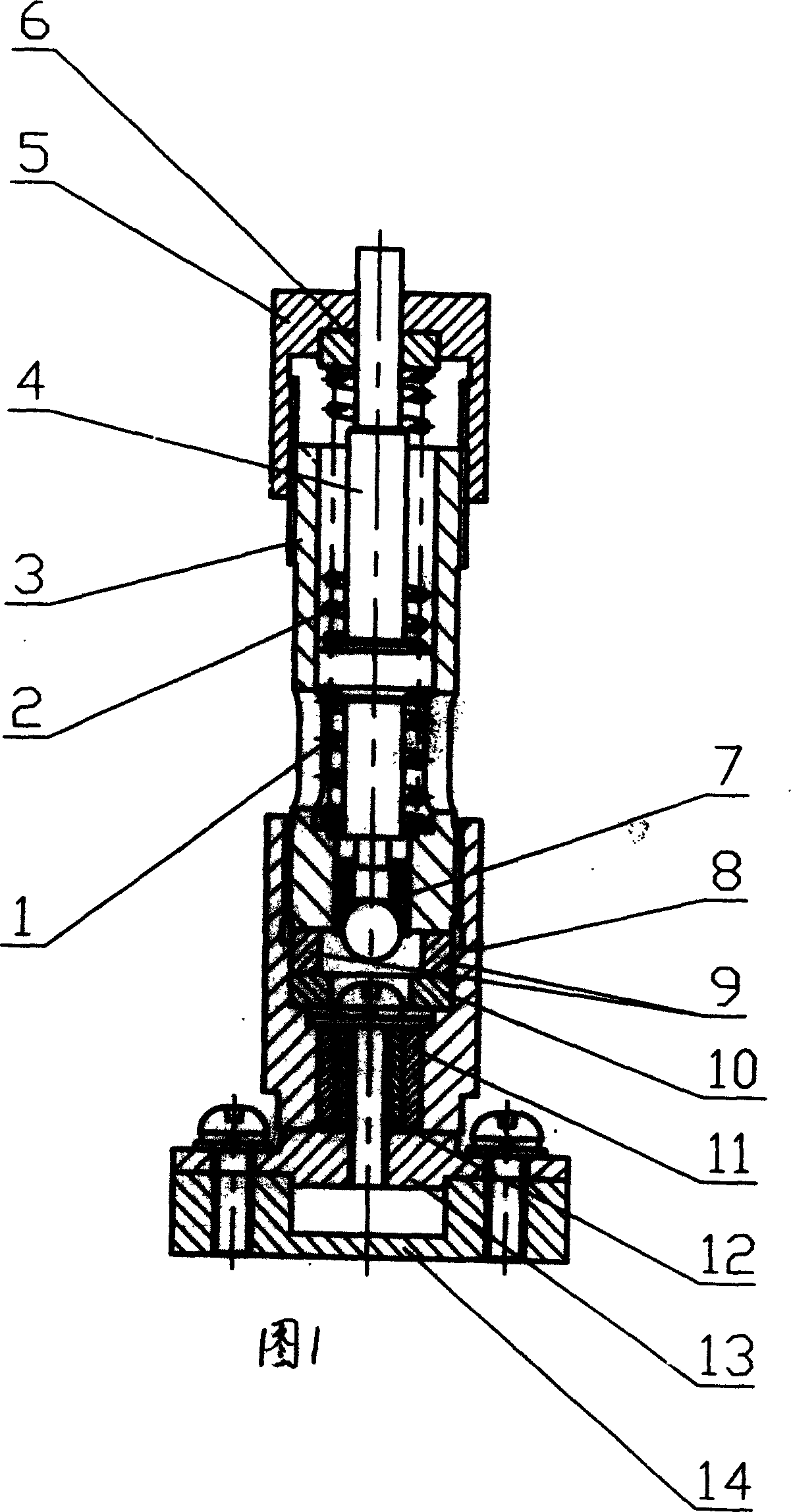

Image

  • Temperature-sensitive driver of door closing apparatus
  • Temperature-sensitive driver of door closing apparatus
  • Temperature-sensitive driver of door closing apparatus

Examples


Embodiment Construction

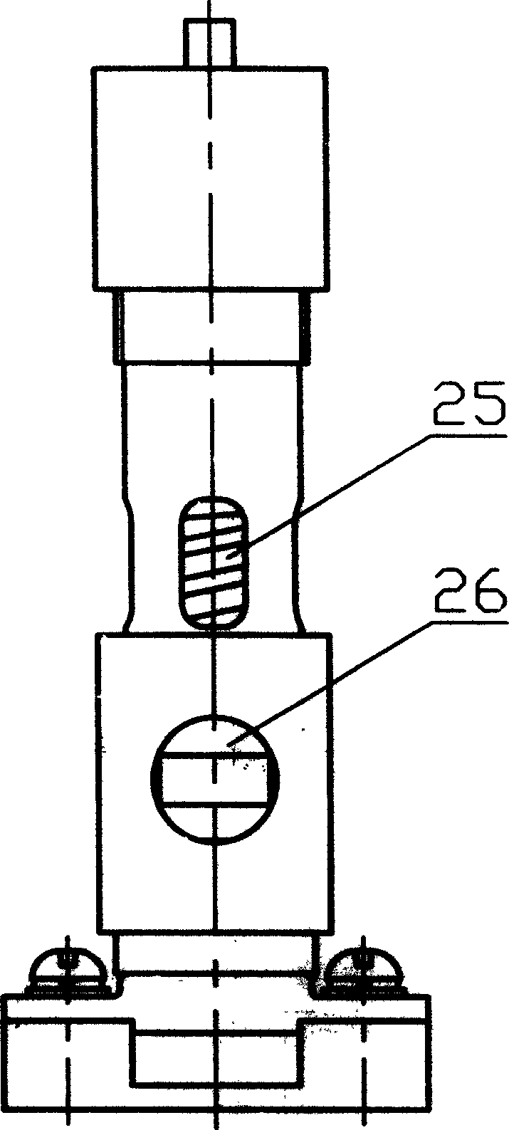
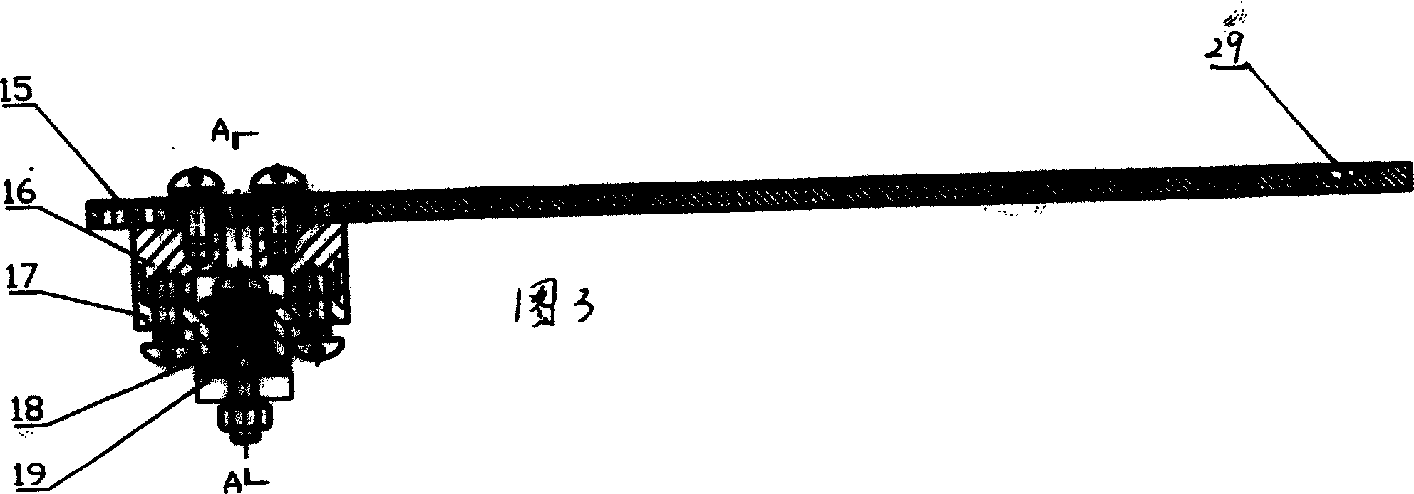
[0013] The accompanying drawings show the structure of the present invention and its embodiments, and further describe the relevant details and working principles of the embodiments in conjunction with the accompanying drawings. The temperature-sensitive driving device of the door closer has a spring sleeve 3 and a support rod 15, and a stepped push rod 4 is arranged inside the spring sleeve 3, and the stepped push rod 4 is a three-step ladder. The top of 4, that is, the first stage is provided with a bias spring 2, and the bottom of the stepped push rod 4, that is, the third stage is provided with a shape memory alloy (shape memory alloy) spring 1, and the shape memory alloy spring 1 is composed of a narrow temperature Made of wide hysteresis memory alloy, it has the characteristics of stable phase transition point, accurate and reliable temperature response, and high sensitivity. The shape memory alloy spring 1 can effectively increase the deformation displacement and increas...


PUM


Abstract

The present invention discloses a heat sensitive driving device for door closer. It is characterized by that in the spring sleeve a stepped pushing bar is set, the upper portion of said stepped pushing bar is equipped with a biasing spring, and the lower portion of said stepped pushing bar is equipped with a shape memory alloy spring, and the tail end of the pushing bar is equipped with a contact. A heat-conducting through groove in cut in the place where the slape memory alloy spring is mounted in the spring sleeve, so that the shape memory alloy spring is exposed to air, on the connecting cover of spring sleeve a central through hole is set, a supporting bar is passed through said central through hole, on the supporting bar a slideway is set, the described contact can be moved in the slideway, and the end head of said slideway is equipped with a recessed pit which can be matched with said contact. Under the action of door closer said invention can make the fire-control access door tightly closed so as to implement protective smoke-resisting and fire-resisting action.

Description

【Technical field】 [0001] The invention relates to a fire fighting device, in particular to a door closer fire door with a fire sensing function. 【Background technique】 [0002] At present, in the field of fire protection technology, relying on fire doors to block smoke and fire can effectively prevent the spread of smoke and endanger life and property, inhibit the development of fire, and protect safe passages. Door closers are commonly used door hardware, and ordinary door closers do not have fire sensing capabilities. At present, the fire induction door closers researched and invented at home and abroad are basically electric, relying on the smoke temperature sensor to monitor the fire, and the door opening and closing action is performed by the motor or electromagnetic locking device. The system structure is complex, and these are power-consuming devices. These are generally realized by electronic components inside the electric fire doors....

Claims


Application Information

Patent Timeline
IPC IPC(8): E05F15/71E05F15/72
Inventor 马仁飞魏宪民
Owner LISHUI SHENFEI LIYI SECURITY PRODS
Learn More