
Method of diagnosing partial discharge in gas-insulated apparatus and partial discharge diagnosing syatem for carrying out the same

A gas-insulated device and partial discharge technology, which is used in gas-insulated substations, switchgear settings, emergency protection devices, etc., can solve the problems of complex internal structure of neural network structure, difficulty in learning convergence, and easy occurrence of minimum values.

Inactive Publication Date: 2005-01-19
HITACHI LTD
View PDF1 Cites 8 Cited by
  • Summary
  • Abstract
  • Description
  • Claims
  • Application Information

AI Technical Summary

Problems solved by technology

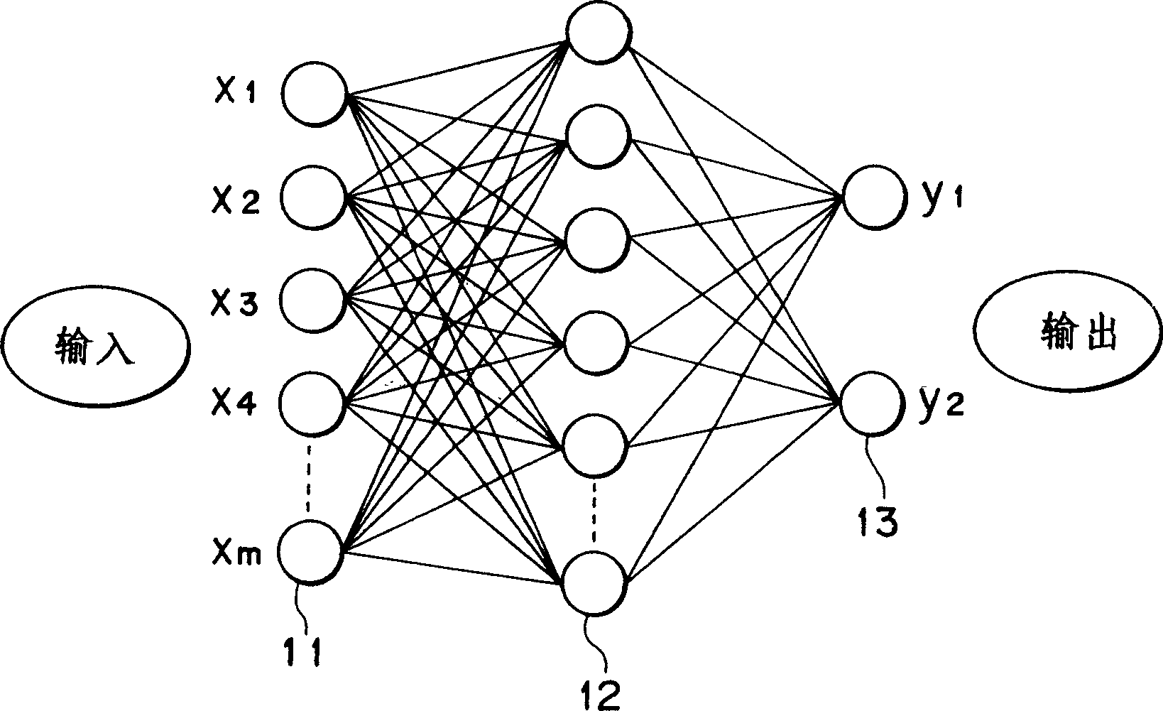
However, since the input layer 41 and the output layer 43 each have a lot of nodes, this makes the internal structure of the neural network structure complex, so it appears that the learning of known data is difficult to converge, local minimum values ​​are easy to appear, and require a particularly long learning time. The problem
In particular, it is difficult to achieve a practically acceptable accuracy for diagnosing

Method used


Image

  • Method of diagnosing partial discharge in gas-insulated apparatus and partial discharge diagnosing syatem for carrying out the same
  • Method of diagnosing partial discharge in gas-insulated apparatus and partial discharge diagnosing syatem for carrying out the same
  • Method of diagnosing partial discharge in gas-insulated apparatus and partial discharge diagnosing syatem for carrying out the same

Examples


Embodiment Construction

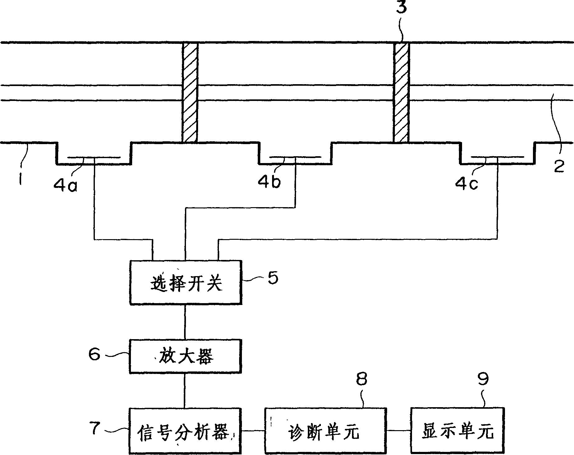
[0046] refer to figure 1 and 2 Preferred embodiments of the present invention are described. figure 1 is a block diagram of a partial discharge diagnostic system in a preferred embodiment of the present invention for diagnosing partial discharges generated in gas-insulated installations, figure 2 is a flowchart of the diagnostic procedure, through figure 1 The partial discharge diagnostic system shown implements a conditional branch step.

[0047] refer to figure 1 , indicating the grounded metal case 1, the high-voltage conductor 2, the insulating washer 3 holding the high-voltage conductor 2 in the gas-insulated device, and the partial discharge signal detectors 4a, 4b and 4c for detecting electromagnetic waves generated by partial discharge, for selecting the partial discharge Broadband selection switch 5 for one of the discharge signals 4a, 4b and 4c, amplifier 6, signal analyzer 7 such as a spectrum analyzer for frequency analysis or FFT (Fast Fourier Transform) for ...


PUM


Abstract

The present invention provides a method of diagnosing a partial discharge in a gas-insulated apparatus and a partial discharge diagnosing system for carrying out the same to achieve highly accurate diagnosis through the detection of a partial discharge signal and diagnosing the partial discharge signal through multiple conditional branching. The partial discharge diagnosing system of the present invention comprises: a partial discharge signal detector for detecting a partial discharge signal representing a partial discharge produced in the gas-insulated apparatus, a signal analyzer for receiving the partial discharge signal detected by the partial discharge detector and analyzing the partial discharge signal, a diagnostic unit for determining a cause of the partial discharge on the basis of results of analysis made by the signal analyzer, and a display unit for displaying results of diagnosis. The diagnostic unit is provided with a diagnostic means to make multiple conditional branching to a plurality of second diagnostic means according to result of diagnosis made by a first diagnostic means, and obtains a result of diagnosis made by the second diagnostic means, thereby achieving highly accurate diagnosis by detecting the partial discharge signal and subjecting the partial discharge signal to multiple conditional branching.

Description

[0001] The present invention is a divisional application of the No. 00101178.2 patent application filed on January 28, 2000, entitled "Partial Discharge Diagnosis Method and Partial Discharge Diagnosis System in Gas Insulated Devices". technical field [0002] The invention relates to a method for diagnosing partial discharges in gas-insulated installations and a system for diagnosing partial discharges for carrying out such a method. In particular, the present invention relates to a method of diagnosing partial discharge in a gas-insulated device by detecting a partial discharge signal and passing the partial discharge signal through a plurality of stages of conditional transfer for diagnosis, and a partial discharge diagnosis system implementing the method . Background technique [0003] A gas-insulated device, such as a gas-insulated switchgear installed on the main distribution device, generates partial discharges when abnormal insulation conditions occur in the device. ...

Claims


Application Information

Patent Timeline
Patent Type & Authority Applications(China)
IPC IPC(8): H02B3/00G01R31/12H02B5/06H02B13/065H02H1/00
CPCH02H1/0092G01R31/1254H02H1/0015H02B5/06
Inventor 加藤达朗远藤奎将
Owner HITACHI LTD
Learn More