Secondary reforming equipment

An equipment, a technology for reforming gas, applied in combustion equipment, lighting and heating equipment, combustion methods, etc., can solve problems such as unsatisfactory refractory materials, short life of oxygen feed pipes, etc., to reduce the number of shutdowns, The effect of long operating life

Inactive Publication Date: 2005-01-19
CASALE CHEM SA
View PDF0 Cites 2 Cited by
  • Summary
  • Abstract
  • Description
  • Claims
  • Application Information

AI Technical Summary

Problems solved by technology

However, due to the high temperature in the combustion chamber, especially at the tube tip, refractory materials have proven unsatisfactory from a long-term point of view. Therefore, in order to meet the above-mentioned requirements, the life of the oxygen feed pipe in the prior art equipment is still Short-lived

Method used


Image

  • Secondary reforming equipment
  • Secondary reforming equipment

Examples


Embodiment Construction

[0026] refer to figure 1 , numeral 1 generally designates a secondary reformer of this type comprising a substantially cylindrical housing 2, in which is placed a catalytic bed 3 carrying out a secondary reaction, such as a steam reforming reaction, to produce synthesis gas.

[0027] At the top end of the casing 2 , generally frusto-conical, a combustion chamber 4 is defined for burning hydrocarbons, and at the lower end of the casing 2 , a compartment 5 is defined for collecting the synthesis gas produced in the catalytic bed 3 . The combustion chamber 4 and the compartment 5 are in fluid communication with said catalytic bed 3 .

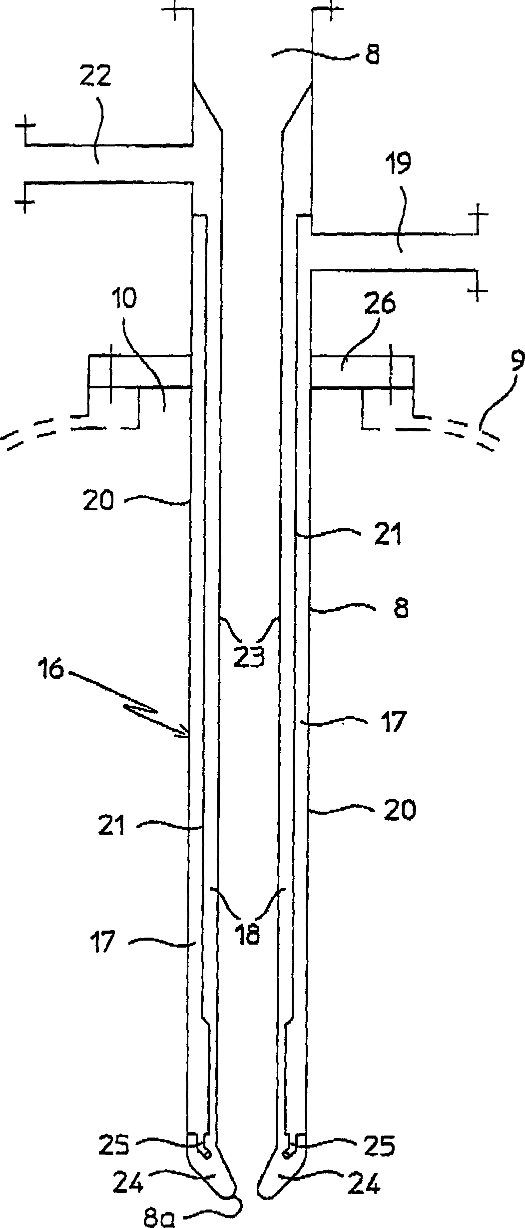
[0028] Above the conical portion delimiting the combustion chamber 4, the casing 2 ends with an upper cylindrical appendage 2a of smaller diameter, which is the casing of the vertical duct 7 feeding reformed gases (hydrocarbons) to the combustion chamber 4 . Inside the conduit 7, a vertical tubular oxygen feed pipe 8 is installed, coaxial with th...


PUM


Abstract

A secondary renormalization equipment for burning a portion of renormalized gas with oxygen which comprises a catalyzing bed, firing chambers are arranged on the catalyzing bed in fluid connection, and a tool for feeding the gas flow containing oxygen and part of the renormalized gas into the combustion chambers.

Description

technical field [0001] The present invention relates to a device suitable for secondary reforming reactions. [0002] In particular, the present invention relates to a secondary reforming reaction plant for the production of a gas mixture comprising hydrogen and carbon monoxide, such as ammonia or methanol. [0003] More specifically, the secondary reformer according to the present invention is specially designed for the combustion of partially reformed gas with oxygen, comprising: [0004] - catalytic bed; [0005] - a combustor above and in fluid communication with said catalytic bed; [0006] - Means for separately feeding a gas stream comprising oxygen and a gas stream comprising partially reformed gas into said combustion chamber. [0007] In the field of secondary reforming reactions, this equipment is also called secondary reforming furnace or autothermal reforming furnace. [0008] In the following description and appended claims, the term "oxygen-comprising gas st...

Claims


Application Information

Patent Timeline
Patent Type & Authority Applications(China)
IPC IPC(8): B01J8/02B01J19/26C01B3/38
CPCC01B2203/1276F23C2900/07021B01J2219/00119C01B2203/142C01B3/382B01J8/0278C01B2203/0844F23D2214/00B01J8/025B01J19/26C01B2203/0244C01B2203/82B01J4/002
Inventor 詹弗兰科·贝代蒂
Owner CASALE CHEM SA
Why Eureka
Try Eureka