
Field transmission magnetosensitive sensor

A magnetic sensor and field emission technology, applied in the field of magnetic sensors, can solve the problems of unsatisfactory thermal conductivity, easy damage to the top of the emitter, complicated manufacturing process, etc., and achieve low cost, improved life and sensitivity, and simple manufacturing process. Effect

Inactive Publication Date: 2004-12-08
UNIV OF ELECTRONICS SCI & TECH OF CHINA
View PDF0 Cites 2 Cited by
  • Summary
  • Abstract
  • Description
  • Claims
  • Application Information

AI Technical Summary

Problems solved by technology

However, because the emission tip is very thin, the vacuum degree is very high during the working process, otherwise the top of the emitter is easily damaged due to the rebound of the particles, and the actual field emission comes from a small area on the top of the emitter, where the emission The current density is very high. At the same time, due to the unsatisfactory thermal conductivity of molybdenum and silicon, the temperature at this place will be high during emission, resulting in short life, and the manufacturing process is more complicated and the cost is relatively high.

Method used


Image

  • Field transmission magnetosensitive sensor
  • Field transmission magnetosensitive sensor
  • Field transmission magnetosensitive sensor

Examples


Embodiment Construction

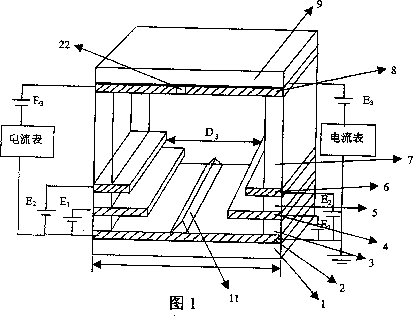
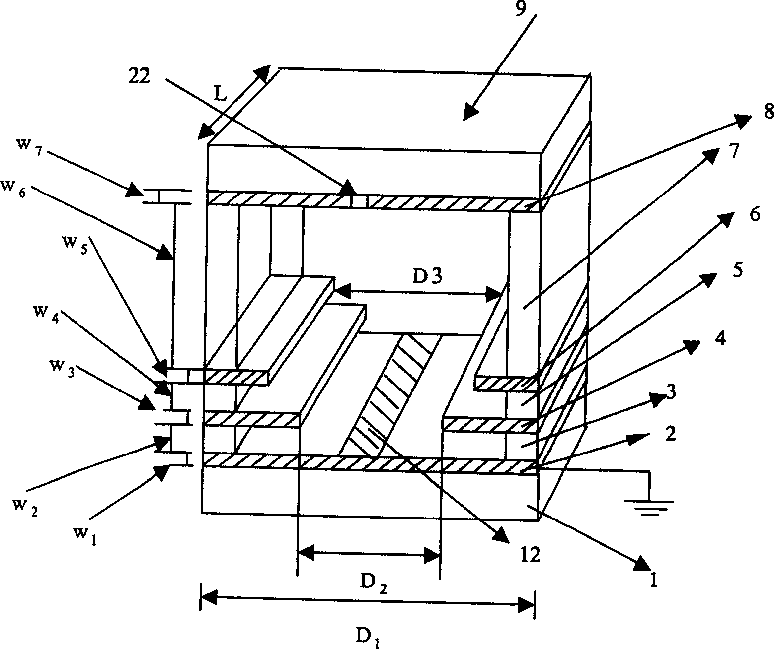
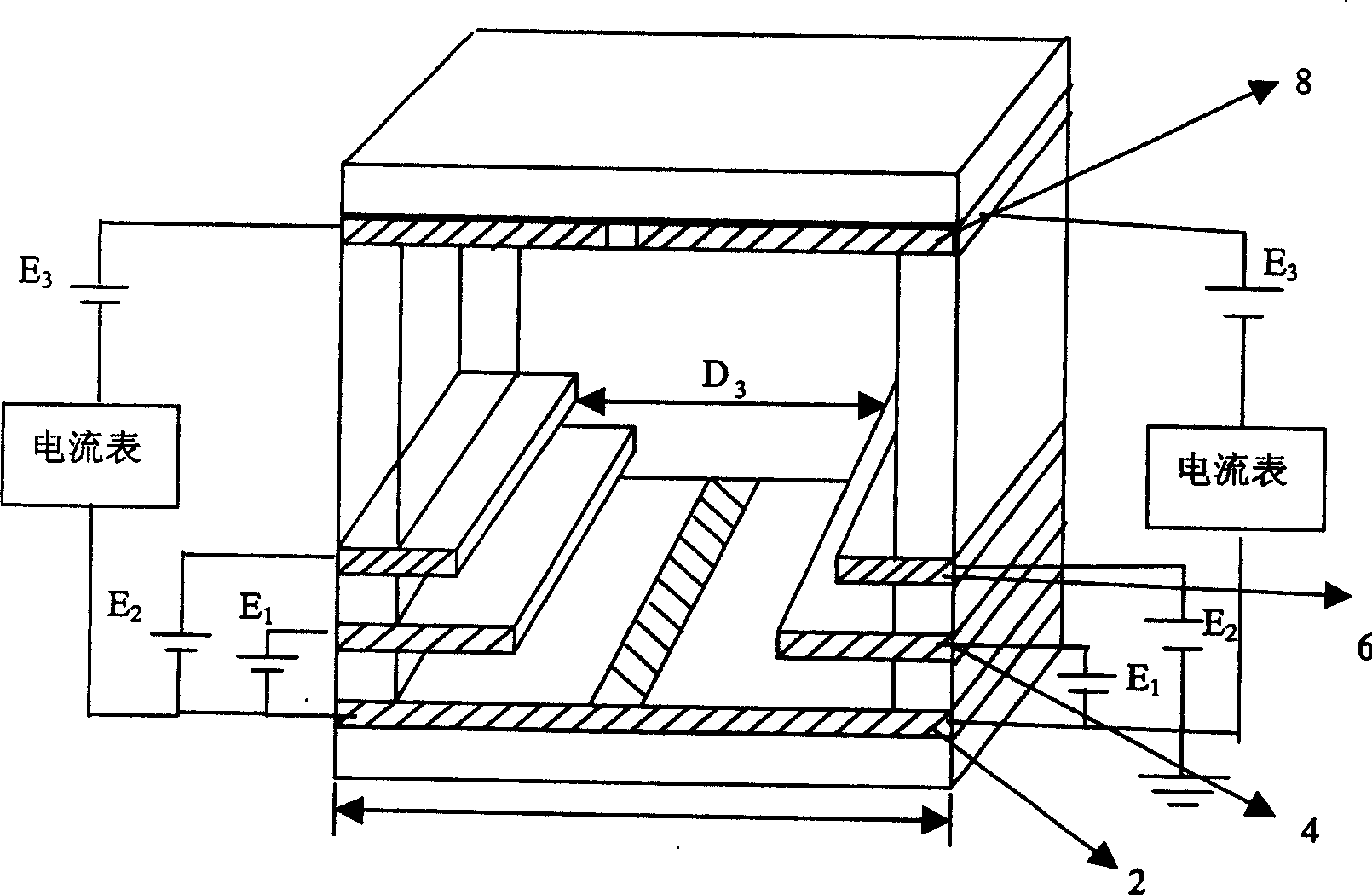
[0018] The present invention will be described more clearly below through detailed embodiments and with reference to the accompanying drawings. However, the listed embodiments of the present invention are only for describing the present invention in detail, and the embodiments of the present invention can have various forms, so the protection scope of the present invention is not limited to the embodiments.

[0019] Refer to attached figure 2 , the present invention has a lower substrate 1, the first metal film 2 is on the lower substrate 1, the thickness W 1 About 1μm, length D 1 About 1mm, the first insulating film 3 is on the first metal film 2, and its thickness W 2 About 10 μm; the second metal film 4 is on the first insulating film 3, and its thickness W 3 About 1 μm, the second insulating film 5 is on the second metal film 4, and its thickness W 4 About 4 μm; the third metal film 6 is on the second insulating film 5, and its thickness W 5 About 1 μm. The middle fi...


PUM


Abstract

A magnto transducer consists of bottom base, the first metal film, the first insulation film, the second metal film, the second insulation film, the third metal film, isolator, top base, positive electrode and insulation film as well as film located at centre of the first metal film and used as electron source of field emission. The film can be made by carbon nanotube film or by diamond film.

Description

Technical field: [0001] The invention belongs to the field of electronic technology, and in particular relates to a magnetic sensitive sensor. Background technique: [0002] The traditional sensors that use the Hall effect to detect the magnetic field strength usually first grow compound semiconductor thin films, then form components through photolithography, steam tube and other precision processing, and finally package them in plastic. The principle is to use the electrons in the semiconductor to deflect under the magnetic field to obtain the magnetic field strength to be measured. Since electrons move in semiconductors, compared with electrons moving in vacuum, their movement speed and sensitivity are greatly limited, and their working environment will also be limited by high temperature and nuclear radiation. [0003] The paper "Fieldmission magnetic sensors based on focusing devices" (Solid-State Electronics 45 (2001) 977-986) published by M.I.Marques and P.A.Serena on...

Claims


Application Information

Patent Timeline
Patent Type & Authority Applications(China)
IPC IPC(8): G01R33/02
Inventor 曾葆青田时开杨中海
Owner UNIV OF ELECTRONICS SCI & TECH OF CHINA
Learn More