
Automatic foot path

A technology for moving walks and structural parts, applied in escalators, transportation and packaging, etc., can solve the problems of fast falling speed, violent collision between the entrance and exit floors, and the braking device of wheelchairs cannot be released in time, so as to achieve thinning and smooth passenger movement. Effect

Inactive Publication Date: 2004-11-03
HITACHI LTD
View PDF1 Cites 3 Cited by
  • Summary
  • Abstract
  • Description
  • Claims
  • Application Information

AI Technical Summary

Problems solved by technology

[0004] In the above prior art, although it has great advantages in terms of ease of installation and construction, there are various problems in the prior art: since the pedal is set to move through a steep slope from the installation floor at a high position Passages and short-distance horizontal moving passages enter the entrance and exit floors, so passengers, especially those in wheelchairs, must withstand relatively drastic changes in the up and down directions within a short distance to the exit. Dangerous factors, such as the brake device of the wheelchair not being released in time, the rapid descent, the violent collision with the top of the entrance and exit floor, and the fear caused by the fact that most of the pedal moving channel moves at a high place, etc.
Therefore, when passengers, especially elderly passengers, step into the moving walkway from the entrance, it is difficult to judge whether the pedals that move roughly in the horizontal direction are actually moving, and it is also difficult to judge how fast the pedals are moving, so it is difficult to grasp the timing of stepping on the pedals

Method used


Image

  • Automatic foot path
  • Automatic foot path
  • Automatic foot path

Examples


Embodiment Construction

[0017] Embodiments of the moving walk of the present invention will be described below with reference to the accompanying drawings.

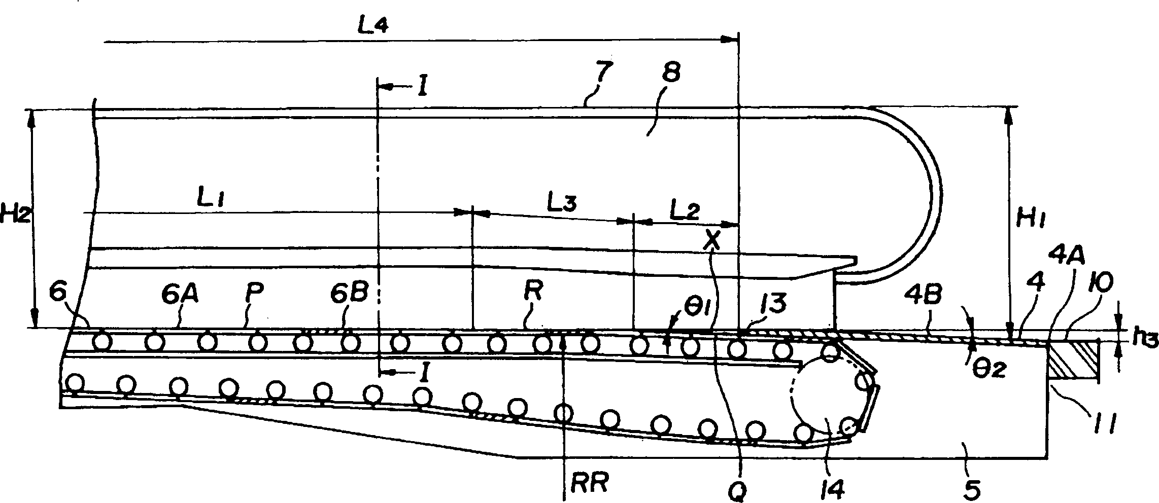
[0018] figure 1 It is a partial cross-sectional overall side view showing an embodiment of the moving walk of the present invention. figure 2 for figure 1 Top view of the part shown. image 3 to represent figure 1 Partial cut-away side view of the main part. Figure 4 for will image 3 Partial cut-away side view showing enlarged main parts. Figure 5 for image 3 Sectional view along line I-I.

[0019] Such as figure 1 As shown, the moving walkway 1 is composed of a structural part and a body frame 9, and the above-mentioned structural part is connected in a circular manner, from the entrance and exit floor (at the entrance) 2 and the machine room 3 at one end towards the entrance and exit floor (at the exit) 4 at the other end and The mechanical chamber 5, the pedal 6 that moves on a moving channel that is horizontal or has an inc...


PUM


Abstract

The pallet 6 moving substantially horizontally to convey a passenger is composed of ordinary color pallets 6A and colored pallets 6B arranged at a predetermined interval. A height position of a substantially horizontal main moving road surface P of the pallet 6 is substantially the same as a height position of a top face of a getting-on-and-off floor 4 upper face or is slightly higher than the latter position. An inclined road surface Q on which a getting-on-and-off floor 4 side is lower than the main moving road surface P is provided in a part where the pallet 6 comes in and out of the getting-on-and-off floor 4. An inclined floor surface 4B which is continuous with the inclined road surface Q and on which an anti-pallet side becomes low is provided on the getting-on-and-off floor 4. To provide a moving sidewalk allowing a passenger, in particular, a wheelchair user to move smoothly between a pallet and a floor side and capable of easily determining operation of the pallet and reducing thickness of a device.

Description

technical field [0001] The present invention relates to a moving walkway that transports passengers by pedals connected in a circular manner and moving in a substantially horizontal direction. Background technique [0002] Recently, a large number of moving walkways for transporting passengers have been constructed at airports, stations, sightseeing facilities, etc. And, as a kind of moving walk that is convenient for installation and construction, a following technical solution is proposed, that is, only the machine room part at both ends of the pedal moving passage is buried under the installation floor surface, and other moving passage parts are installed on the installation floor. Above the floor surface, so as to control the construction method of the pit construction within a minimum range (refer to patent document 1). [0003] Patent Document 1: Japanese Patent Application Laid-Open No. 2-310290 (line 1 in the lower right column on page 2 to line 13 in the upper ...

Claims


Application Information

Patent Timeline
Patent Type & Authority Applications(China)
IPC IPC(8): B66B29/08B66B21/10B66B23/00B66B23/08B66B23/12
Inventor 斋藤忠一宇津宫博文小嶋和平
Owner HITACHI LTD
Learn More