Finger cutter

A milling cutter and cutter body technology, applied in the field of finger joints, can solve the problems of large damage, reduced blade toughness, and unusable milling cutters, etc., to improve wear resistance, supplement wear resistance, and wear resistance is effective Effect

Inactive Publication Date: 2004-10-20
KANEFUSA HAMONO KOUGIYOU KK
View PDF0 Cites 3 Cited by
  • Summary
  • Abstract
  • Description
  • Claims
  • Application Information

AI Technical Summary

Problems solved by technology

[0003] However, since the edge of the blade is formed with a high-hardness material, the toughness of the blade is reduced, which causes the chipping of the blade, and is particularly prone to damage from the root of the blade or its near side. A chipped edge can render the cutter nearly unusable
Therefore, it is necessary to replace the replaceable edge or the milling cutter, which is extremely damaging compared to the simple wear of the cutting edge

Method used


Image

  • Finger cutter
  • Finger cutter
  • Finger cutter

Examples


Embodiment Construction

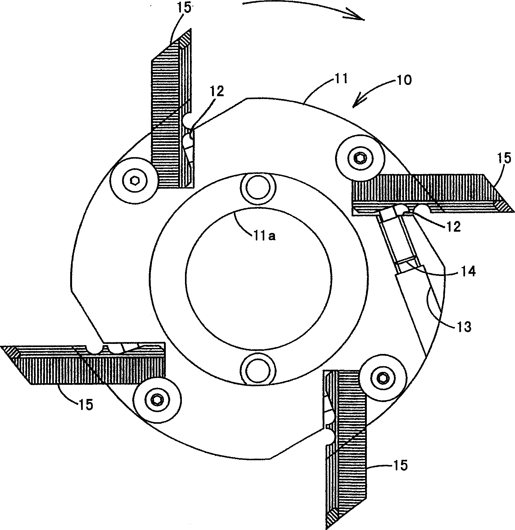
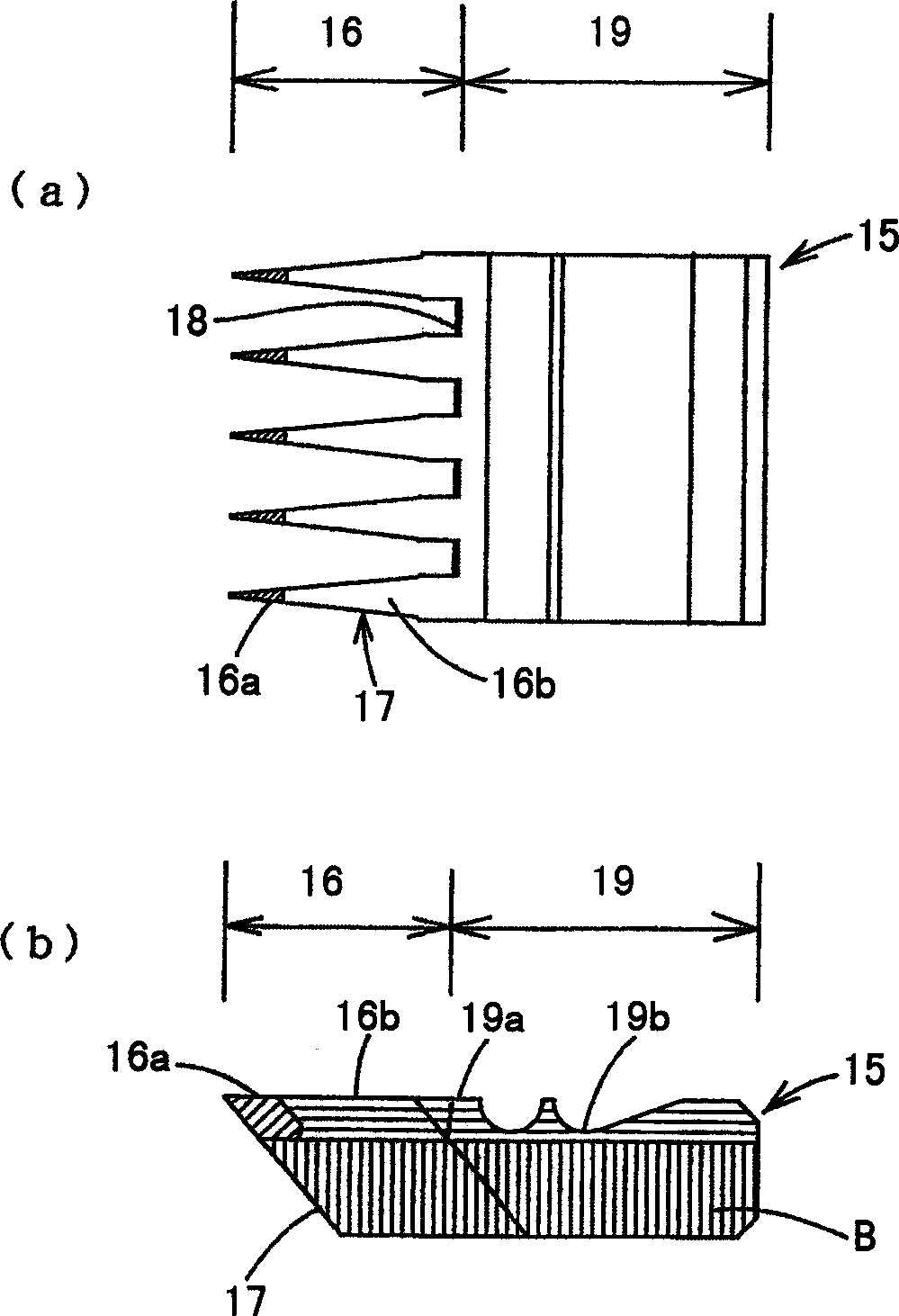
[0015] An embodiment of the present invention will be described below using the drawings. figure 1 is a side view of the replaceable edge finger milling cutter according to this embodiment, figure 2 It is a front view and a side view of the replaceable edge 15.

[0016] The finger milling cutter 10 is provided with a steel cylindrical cutter body 11. The center of the cutter body 11 has a central hole 11a for inserting into the main shaft, and four places in the circumferential direction of the peripheral wall of the cutter body 11 are provided with holes extending in the axial direction. The mount 12. The mounting seat 12 is inclined about 30° toward the front of the rotation direction with respect to the radial direction, and is a recess cut into a substantially rectangular shape. The replaceable blade 15 is inserted into the mounting seat 12 . On the outer periphery of the cutter body 11, a mounting hole 13 communicating with the mounting base 12 from the rotation fron...


PUM


Abstract

Cutting portion regions 16 of replaceable blades 15 that extrude outward in a radial direction at a plurality of portions in a peripheral direction of an outer periphery of a body 11 of a finger joint cutter are arranged in that, as for a cutting portion material that comprises cutting edge, tip end cutting portions 16a are formed of a steel material of high hardness and base portion side cutting portions 16b, which are the remaining portions, are formed of a steel material that exhibits a higher toughness than that of the tip end cutting portions. It is possible to improve the wear resistance through the tip end cutting portions and to improve the chipping resistance by the base portion side cutting portions. The steel material of high hardness comprising the tip end cutting portions and the steel material of high toughness comprising the base portion side cutting portions are successively joined through forge welding.

Description

technical field [0001] The present invention relates to a finger milling cutter as a rotary cutting tool for machining a finger joint joint as a joint of wood or the like. Background technique [0002] Such as Figure 5 As shown, the finger milling cutter 1 has a plurality of mountain-shaped wedge-shaped blades 3 that protrude radially outward at multiple places in the circumferential direction of the outer periphery of the cutter body 2, and a plurality of wedge-shaped blades 3 are formed at the end of the material M to be cut by the blades 3. Comb-shaped finger joint F with a thin and deep groove. Because deep grooves are processed in this way, the degree of wear of the edge of the edge of the blade 3 of the finger milling cutter 1 will vary greatly due to the position of the edge of the edge, especially the edge of the groove bottom of the cutting finger joint joint. There is more wear on the edge of the blade near the front end. Like this, if the wear of the blade edge...

Claims


Application Information

Patent Timeline
Patent Type & Authority Applications(China)
IPC IPC(8): B23P15/28B27F1/16B27G13/14
CPCB27F1/16B27G13/14B23P15/28
Inventor 曾我胜明土屋敦
Owner KANEFUSA HAMONO KOUGIYOU KK
Why Eureka
Try Eureka