Direct conversion receiver with DC offset compensation function and its compensation method

A DC offset and receiver technology, applied in DC coupled DC amplifiers, amplifiers with semiconductor devices/discharge tubes, oscillation conversion angle demodulation, etc., can solve problems such as long charging time

Active Publication Date: 2004-10-13
VIA TECH INC
View PDF1 Cites 12 Cited by
  • Summary
  • Abstract
  • Description
  • Claims
  • Application Information

AI Technical Summary

Problems solved by technology

[0011] However, due to the long charging time of the capacitor in the track and hold circuit, the above-mentioned receiver needs a long time to complete the compensation of the DC offset

Method used


Image

  • Direct conversion receiver with DC offset compensation function and its compensation method
  • Direct conversion receiver with DC offset compensation function and its compensation method
  • Direct conversion receiver with DC offset compensation function and its compensation method

Examples


Embodiment Construction

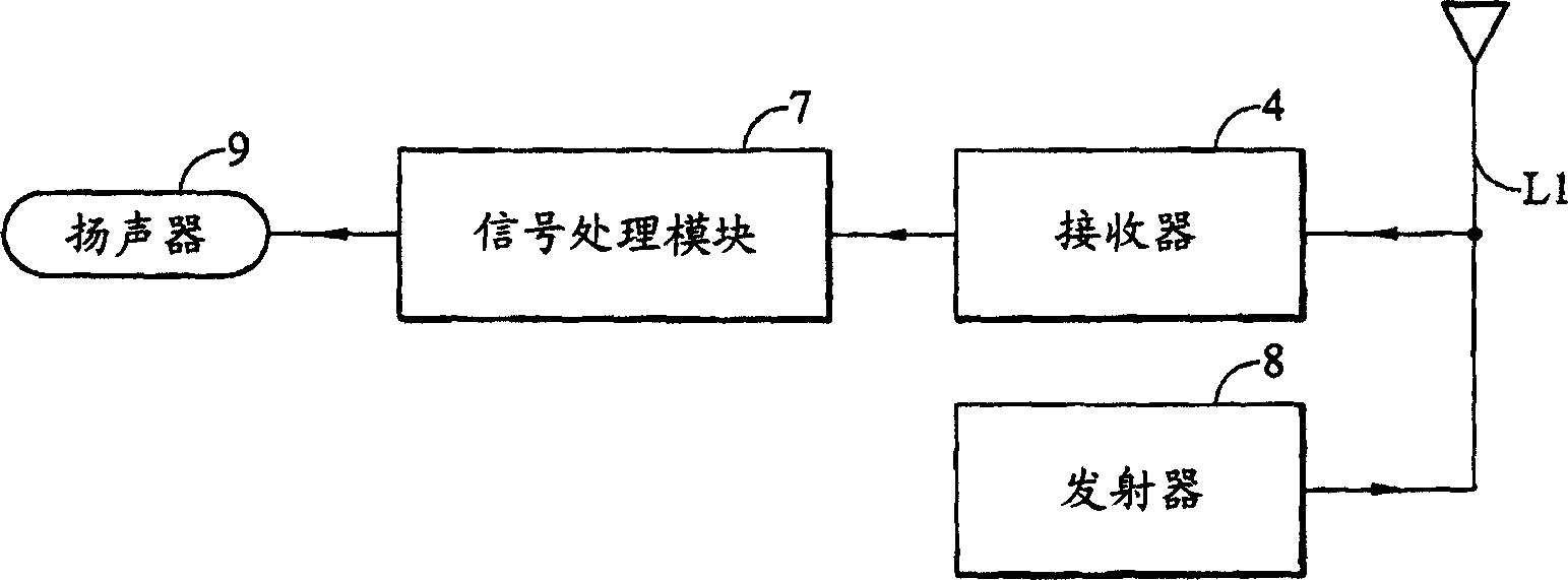
[0052] figure 2 The receiving path of a mobile phone is shown. The receiving path includes an antenna 61 , a radio frequency receiver 4 , a signal processing module 7 and a speaker 9 . The receiver 4 is connected between the antenna 61 and the signal processing module 7 , and the signal processing module 7 is connected to the speaker 9 . The mobile phone also includes a transmission path formed by a transmitter 8 connected to an antenna 61 . The receiver 4 usually comprises an array of amplifiers separated by frequency conversion circuits such as mixers to extract the information carried by the weak signal voltage present at the output of the antenna. The receiver 4 outputs a baseband signal to the signal processing module 7 for further signal processing.

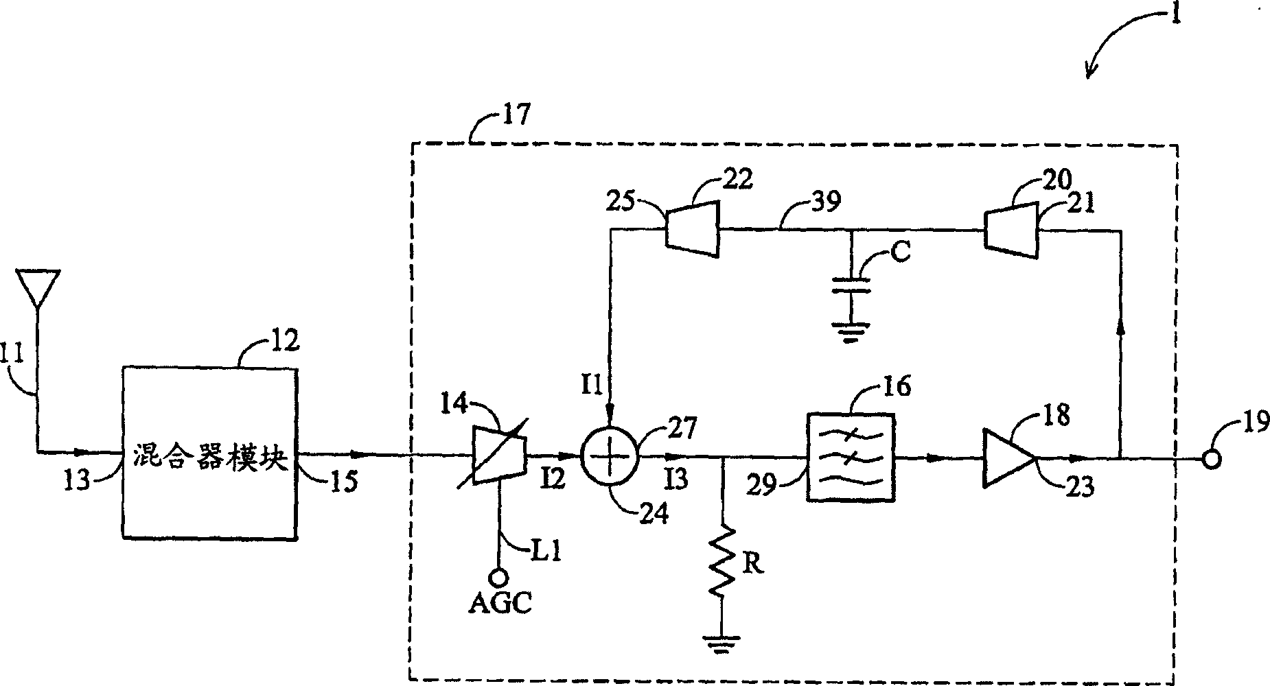
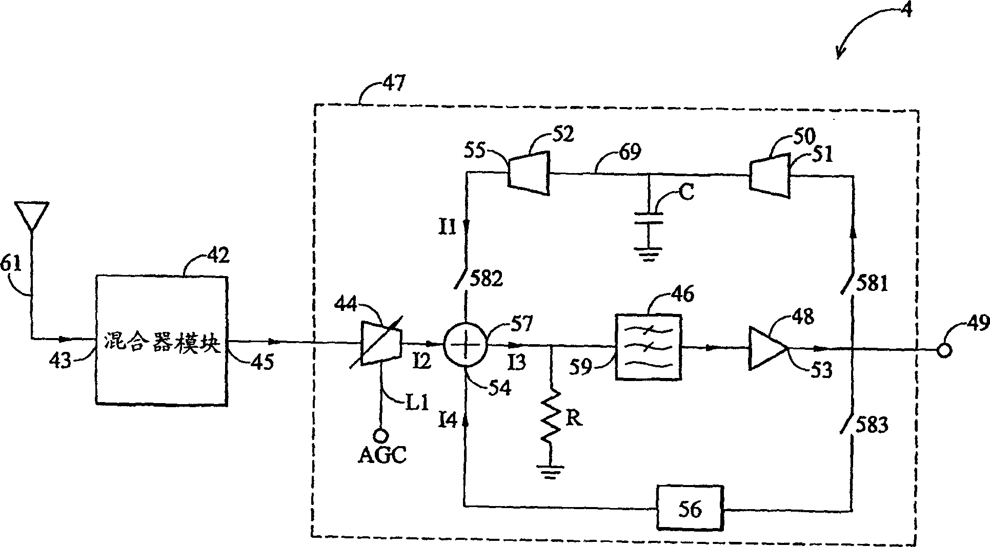
[0053] image 3 A direct conversion receiver in one embodiment of the invention is shown. It includes a mixer module 42 and an amplifier module 47 . The mixer module 42 has an input terminal 43 and an output terminal...


PUM


Abstract

The invention provides a kind of direction transfer receiver which has direct current offset compensating function. It includes a antenna, a mixer module, a automatic gain control amplifier, a adder, a direct offset eliminating circuit, a tracing and maintaining circuit and a switching circuit. The antenna receives a radio frequency signal which has a carrier frequency. The mixer module transfers the radio frequency signal into base frequency signal. The automatic gain control amplifier amplifies the base frequency signal. The adder subtracts the direct offset current from the base frequency signal. The direct current offset eliminating circuit acquires the direct current offset value of the digital signal, and transfers it into direct current offset current. The tracing and maintaining circuit receives the base frequency signal, and maintains the direct current offset voltage on the capacitance, and transfers it into direct current offset current. The switching circuit switches the direct current offset eliminating circuit and tracing and maintaining circuit to receive the base frequency signal.

Description

technical field [0001] The present invention relates to a direct conversion receiver, in particular to a direct conversion receiver with DC offset compensation function used in mobile phones. Background technique [0002] In a digital communication system, a transmitted signal is generated by mixing digital data with a carrier after modulation. Digital signals are usually transmitted in bursts, and each burst contains multiple data bits. When the transmitted signal is received, the data must be returned through the steps of demodulation. [0003] The basic architecture of a wireless receiver usually uses a direct conversion receiver to demodulate received signals. It uses a local oscillator with the same carrier frequency to down-convert the received signal to generate in-phase and quadrature fundamental frequency signals. Direct conversion receivers have the advantages of low cost and low power consumption. The main purpose of direct down-conversion is to down-convert t...

Claims


Application Information

Patent Timeline
Patent Type & Authority Applications(China)
IPC IPC(8): H03D3/00H03F3/45H03G3/30H04B1/30
CPCH03F3/45977H03F2200/294H04B1/30H03G3/3052H03F2200/372H03D3/008
Inventor 陈培炜
Owner VIA TECH INC
Why Eureka
Try Eureka