Intelligent high-precision dynamic reactive compensation control system

A compensation control, high-precision technology, applied in reactive power compensation, reactive power adjustment/elimination/compensation, etc., can solve the problems of poor detection accuracy of detection circuit, large error of switching capacitor capacity, compensation failure, etc., and achieve fast compensation And the effect of accuracy and high measurement accuracy

Active Publication Date: 2013-04-03
HUNAN SENNENG ELECTRIC POWER TECH
View PDF3 Cites 4 Cited by
  • Summary
  • Abstract
  • Description
  • Claims
  • Application Information

AI Technical Summary

Problems solved by technology

[0005] The circuit design is complex, the detection and sampling accuracy is poor, the calculation of reactive power has large errors, the compensation accuracy is poor, the response speed is slow, and the ability to resist harmonic interference is weak. When the power grid has large fluctuations, it is easy to malfunction
On the other hand, due to the poor detection accuracy of the detection circuit, the switching capacitor bank is only judged according to the current grid parameters, and the switching capacitor capacity has a large error, so switching oscillations often occur
Long-term vibration can easily cause problems in the capacitor bank or composite switch, which will cause compensation failure and affect the power supply quality of the power system
[0006] At the same time, the above control system is based on the power factor physical quantity as the main control quantity. In the case of fast reactive power changes, the sampling accuracy is extremely poor, resulting in poor compensation accuracy.
[0007] The control compensation method can only achieve common compensation, resulting in three-phase compensation and compensation balance, and it is also prone to over-compensation or under-compensation
[0008] Furthermore, the control system has only one capacitor capacity encoding program, and each capacitor capacity is the same, and it is easy to cause over-compensation or under-compensation of a certain phase during compensation.

Method used


Image

  • Intelligent high-precision dynamic reactive compensation control system
  • Intelligent high-precision dynamic reactive compensation control system
  • Intelligent high-precision dynamic reactive compensation control system

Examples


Embodiment Construction

[0032] The present invention will be further described in detail below in conjunction with the accompanying drawings, so that those skilled in the art can implement it with reference to the description.

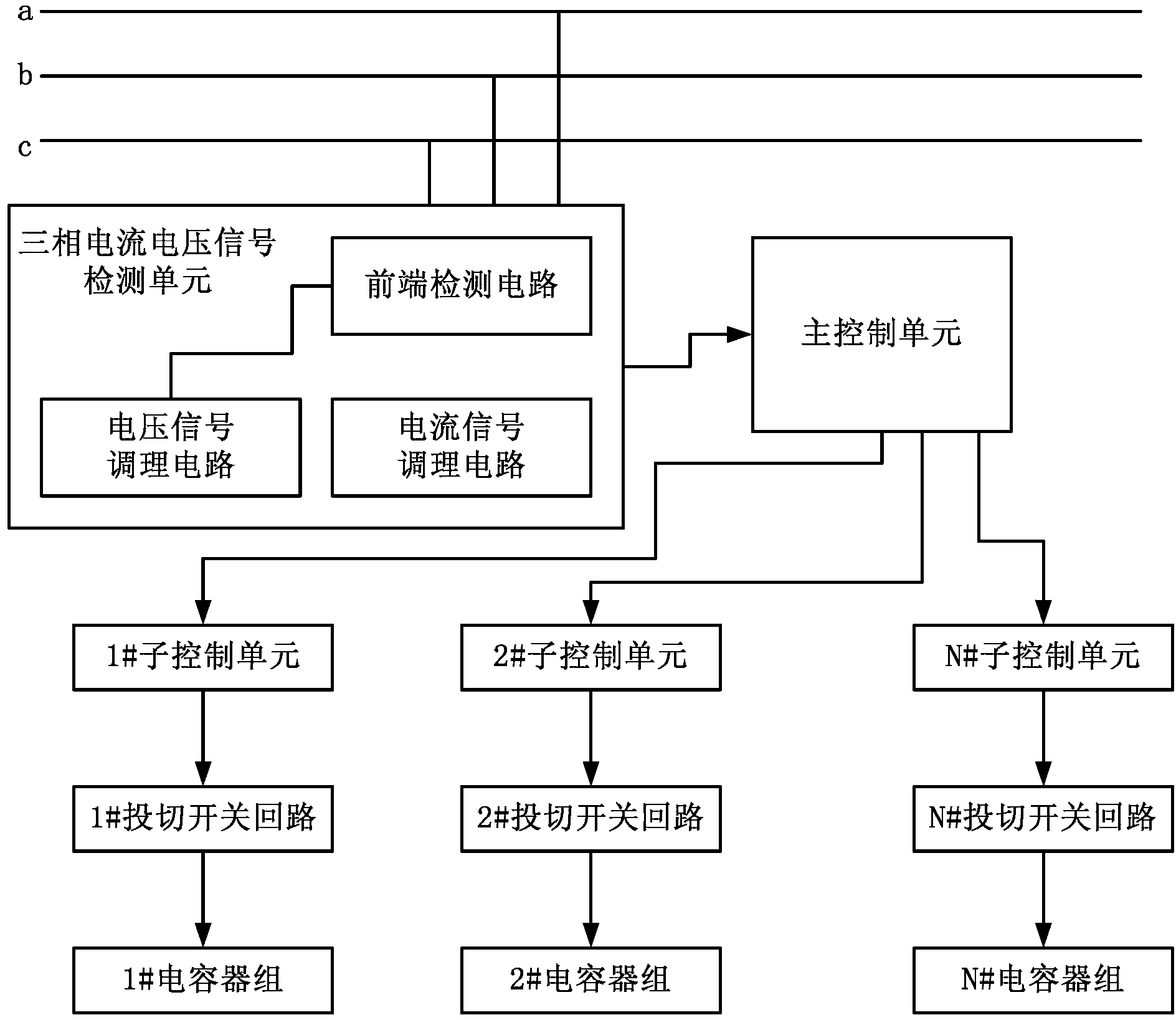
[0033] Such as figure 1 As shown, the intelligent high-precision dynamic reactive power compensation control system described in the present invention includes a plurality of capacitor banks and corresponding switching circuits of capacitor banks, that is, figure 1 1# capacitor bank, 2## capacitor bank, .......N# capacitor bank, and 1# switching circuit, 2# switching circuit, ... N# switching switch circuit. It also includes a three-phase current and voltage signal detection unit, a main control unit, and sub-control units arranged in each capacitor bank switching circuit (that is, 1# sub-control unit corresponding to 1# switching circuit, corresponding to 2# switching circuit The 2# sub-control unit of switching circuit, ... corresponds to the N# sub-control unit of N# swi...


PUM


Abstract

The invention discloses an intelligent high-precision dynamic reactive compensation control system comprising a plurality of capacitor groups and corresponding capacitor group switching switch loops thereof. The intelligent high-precision dynamic reactive compensation control system further comprises a three-phase current and voltage signal detecting unit, a master control unit and auxiliary control units, wherein the auxiliary control units are respectively arranged in the capacitor group switching switch loops; the three-phase current and voltage signal detecting unit is used for detecting three-phase current signals and three-phase voltage signals and transmitting detecting results to the master control unit; the master control unit calculates reactive compensation quantity to be invested according to the received three-phase current signals and the three-phase voltage signals and transmits commands to the corresponding auxiliary control units according to built-in programs, and the corresponding auxiliary control units get through the corresponding capacitor group switching switch loops. The intelligent high-precision dynamic reactive compensation control system is high in measuring precision and quick and correct to compensate by investing the calculated reactive compensation quantity to be invested to the corresponding compensation capacitor groups.

Description

technical field [0001] The invention relates to a reactive power compensation control system, in particular to an intelligent high-precision dynamic reactive power compensation control system. Background technique [0002] Reactive power is an important basis to reflect the quality of the power grid, so the power factor is very representative as a parameter of the power system. The corresponding reactive power compensation technology can not only improve the power factor of the grid, minimize the reactive power of the grid, but also reduce network loss, save power, and improve the transmission capacity of lines and transformers. [0003] In the low-voltage power distribution system, most of the electrical equipment are inductive loads, which cause the current phase to lag behind the voltage phase, so that the power energy is consumed on the grid transmission line, resulting in a serious decline in the quality of the grid power supply. Therefore, corresponding compensation m...

Claims


Application Information

Patent Timeline
Patent Type & Authority Applications(China)
IPC IPC(8): H02J3/18
CPCY02E40/30
Inventor 林勇传邓毅
Owner HUNAN SENNENG ELECTRIC POWER TECH
Why Eureka
Try Eureka