
Image writing assembly and image writing apparatus

An image reading device and image reading technology, applied in the directions of transmission, fixing device, image communication, etc., can solve the problems of image influence, position change, temperature rise, etc., to improve assembly, suppress distance change, and ensure driving. The effect of stability

Inactive Publication Date: 2004-09-08
NISCA KK
View PDF0 Cites 9 Cited by
  • Summary
  • Abstract
  • Description
  • Claims
  • Application Information

AI Technical Summary

Problems solved by technology

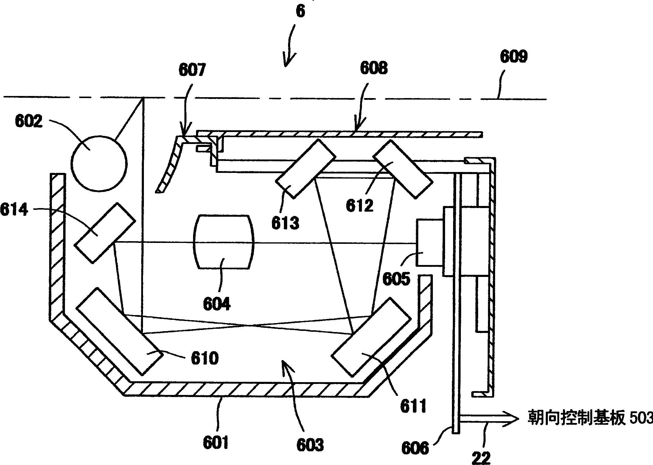
Therefore, when the light source is continuously turned on for a long period of time for continuous reading, there is a problem that heat accumulates inside the holder, the temperature of the board rises, and the position of the mirror changes, which affects the image.

Method used


Image

  • Image writing assembly and image writing apparatus
  • Image writing assembly and image writing apparatus
  • Image writing assembly and image writing apparatus

Examples


Embodiment Construction

[0040] Embodiments of the image reading device for reading images of the present invention will be described below with reference to the accompanying drawings.

[0041] (composition)

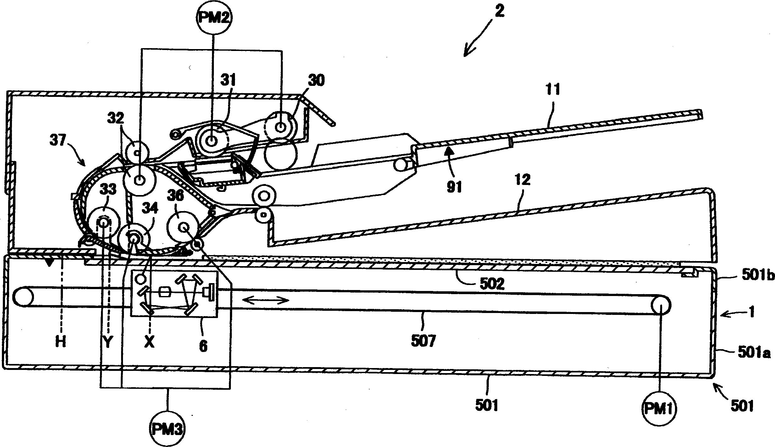
[0042] elephant figure 1 As shown, the image reading device 10 of the present embodiment includes an image reading part 1, which reads an image of a draft; an automatic draft transfer part 2, which is arranged on the image Above the reading unit 1 , the originals are conveyed one by one to a predetermined position where the image reading unit 1 performs a reading process.

[0043]

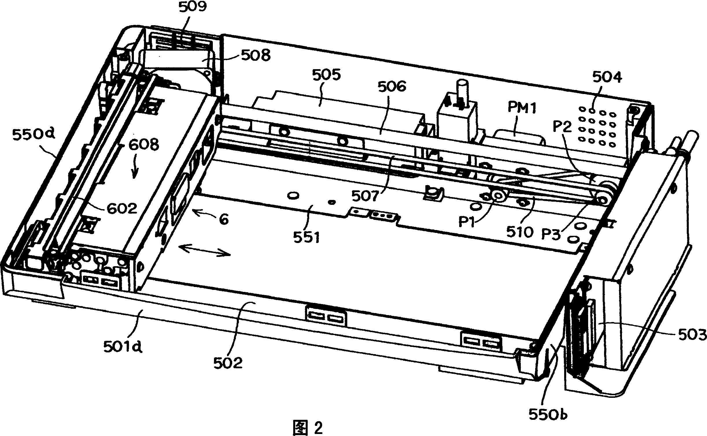
[0044] The image reading unit 1 includes a box-shaped casing 501 made of synthetic resin. The material of the housing 501 is a mixture of acrylonitrile-butadiene-styrene (ABS) and polycarbonate (PC), with a linear thermal expansion coefficient of about 80×10 -5 ( / °C) synthetic resin. The housing 501 is composed of a box-shaped housing bottom 501a and a cover-shaped housing top 501b. The box-shaped housing bott...


PUM


Abstract

The image reading unit is provided with: a xenon lamp; a frame 601 having first and second side walls 60a (60b); a reflection unit for reflecting light reflected on an original; a lens unit for forming an image from the light reflected on the reflection unit; an image sensor for converting the light forming the image in the lens unit to electric signals; first and second supporting plates 750a (750b) disposed on the outer side of the first and second side walls 60a (60b) for supporting the reflection unit. The first reinforcing plate forms a guide unit for supporting the other side of the scanning unit in the main scanning direction and guiding the scanning unit in the sub-scanning direction. The driving source and the drive transmitting unit are fixed to the second reinforcing unit.

Description

technical field [0001] The present invention relates to an image reading device used in a facsimile machine, an image forming device, a scanner used in connection with a computer, and the like. Background technique [0002] A common image reading device includes an image reading unit, which is loaded with an image sensor such as a CCD inside a box-shaped housing, and the image reading unit is moved in the sub-scanning direction, and the image reading unit is fixed to the housing. The manuscript on the upper platen is read and processed. In addition, inside the casing, a drive source for driving a motor or the like of the image reading unit, a timing belt for transmitting drive from the drive source to the image reading unit, and a pair of pulleys around which the timing belt is wound are housed. etc. drive system. [0003] In recent years, in order to reduce the weight of the device and reduce the number of parts, the case has been integrally formed with resin. However, s...

Claims


Application Information

Patent Timeline
Patent Type & Authority Applications(China)
IPC IPC(8): H04N1/03H04N1/10H04N1/193
CPCH04N1/0305H04N1/1017H04N2201/02495H04N2201/02458H04N1/03H04N1/0303H04N1/193H04N2201/0246H04N2201/02462H04N2201/02485
Inventor 由井贤一
Owner NISCA KK
Learn More