
Reinforced concrete roof laying technology and dedicated vacuum tube

A reinforced concrete and vacuum tube technology, applied in the direction of roof, building, building structure, etc., can solve the problem of increasing the compression weight of the lower concrete layer of the roof, failing to achieve mutual involvement and supporting decompression, and increasing the roof slump and crack coefficient. and other problems, to achieve the effect of saving manpower and material resources, reducing manufacturing costs, reducing slump and crack coefficient

Inactive Publication Date: 2004-09-01
李军掴
View PDF0 Cites 4 Cited by
  • Summary
  • Abstract
  • Description
  • Claims
  • Application Information

AI Technical Summary

Problems solved by technology

In addition, due to the poor thermal insulation performance of the reinforced concrete layer, it is necessary to lay a thermal insulation layer
And the insulation layer is installed between the two concrete layers of the roof, so that the roof cannot form an overall structure, and the effect of mutual involvement and supporting decompression cannot be achieved, but it can only increase the compression weight of the lower concrete layer of the roof, making the roof The slump and crack coefficient further increase

Method used


Image

  • Reinforced concrete roof laying technology and dedicated vacuum tube
  • Reinforced concrete roof laying technology and dedicated vacuum tube
  • Reinforced concrete roof laying technology and dedicated vacuum tube

Examples


Embodiment Construction

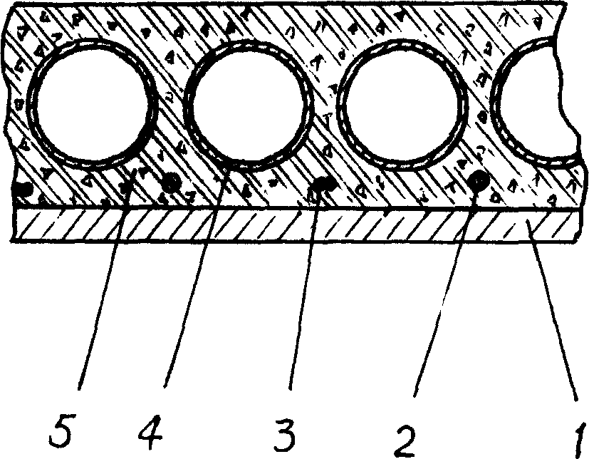
[0013] Reinforced concrete roof pouring technical method of the present invention, combines figure 1 , take the manufacture of a roof with a width of 4 meters as an example to describe in detail:

[0014] a. Support the top form 1 with planks and steel plates.

[0015] b. Lay the steel bars side by side at a height of 20mm from the top form. The steel bars are arranged in the form of main and auxiliary bars at intervals, the diameter of the main bar is 10mm; the diameter of the auxiliary bars is 4mm, two in a bundle. After laying a main reinforcement 2, lay out a bundle of auxiliary reinforcement 3 at a distance of 112mm; then, lay a bundle of main reinforcement 2 at an interval of 112mm...and so on until it is fully paved.

[0016] c. The poured concrete layer is up to 30mm thick.

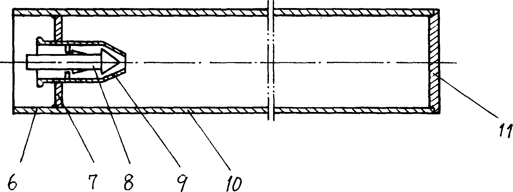
[0017] d. Lay vacuum tubes 4 in the same direction as the steel bars on the concrete layer 5, and each vacuum tube is positioned directly above between two (bundle) steel bars. The diameter (o...


PUM


Abstract

The invention discloses a reinforced concrete roof pouring technique and its special vacuum pipe, its pouring method: a, using wood board and steel plate to put up top mould; b, lay reinforced bars in turn and in parallel on the top mould; c, pour concrete to submerge the reinforced bars; d, lay vacuum pipes on the concrete layer in the same direction to the reinforced bars', where each vacuum pipe is between and above two reinforced bard above; e, pour concrete to the designed thickness; f, vibrate tightly the concrete by plate vibrator, plaster and calendar. It adds heat -protection and -insulation performances to the roof, eliminates the pouring and laying of the concrete layer on the top layer of the roof to reduce the dead weight of the roof, combined with the support decompression function of the vacuum pipe on the roof, obviously reduces subsidence degree and crack coefficient of the roof, enhances the quality of the roof and reduces the construction cost of the roof by 20 % above.

Description

technical field [0001] The invention relates to a building construction method of a roof, in particular to a reinforced concrete roof pouring technology and a special vacuum tube thereof. Background technique [0002] In modern building construction, due to the needs and requirements of seismic performance, the load-bearing floors and roofs between floors are integrally poured with reinforced concrete. The specific method of roof pouring is: first use wood and steel plates to support the top formwork, Then lay the steel bars side by side on the top form in sequence. There are side-by-side and cross-network laying of steel bars. If cross-network structure is adopted, iron wires need to be bound and fixed at each intersection of steel bars. After laying the steel bars, pour concrete until the design thickness, and then vibrate with a plate vibrator. After the solidification period, carry out secondary construction, that is, lay perlite or footstone and other thermal insulati...

Claims


Application Information

Patent Timeline
Patent Type & Authority Applications(China)
IPC IPC(8): E04D7/00
Inventor 李军掴李强王桂珍
Owner 李军掴
Learn More