
Cam type plastic flat filament coiling machine

A technology of plastic flat wire and winder, which is applied in thin material handling, conveying filamentous material, transportation and packaging, etc., can solve the problems of wear of sliders and spiral grooves, high sides at both ends, high power loss, etc. Achieve the effect of smooth reciprocating motion and reversing, easy and smooth movement, and improved winding quality

Inactive Publication Date: 2004-08-25
雁峰集团有限公司
View PDF0 Cites 6 Cited by
  • Summary
  • Abstract
  • Description
  • Claims
  • Application Information

AI Technical Summary

Problems solved by technology

[0002] At present, the flat wire winding machines for plastic wire drawing produced, sold and used at home and abroad all adopt reciprocating screw mechanism to wind up into silk ingots. The reciprocating action of rewinding the silk into a silk ingot; this mechanism has the following defects: the slider runs in the helical groove by forced friction of the slider, so the wear of the slider and the helical groove is quite serious, and in the helical groove There must be a transitional radian at the reversing position of the groove, forming an instantaneous stop, not a real reciprocating constant speed movement, so that the coiled silk spindle has a bamboo-shaped shape and two ends have high or collapsed edges, which greatly affects the winding of the silk spindle In addition, due to the large power loss due to forced sliding friction, the parts are also severely worn
Another reciprocating mechanism of the winding machine is to rely on the rotating cam to push one bearing on each side of the edge to form a reciprocating motion, and to rewind the silk ingot. Because it is pushed by one side when reciprocating, the impact force is relatively large when reciprocating and reversing, causing vibration , after working for a long time, the contact part of the cam will be worn too fast during the reversing, which will affect the winding quality of the silk spindle, and the bamboo-like shape of the silk spindle and the high sides or collapsed edges at both ends will also appear.

Method used


Image

  • Cam type plastic flat filament coiling machine
  • Cam type plastic flat filament coiling machine
  • Cam type plastic flat filament coiling machine

Examples


Embodiment Construction

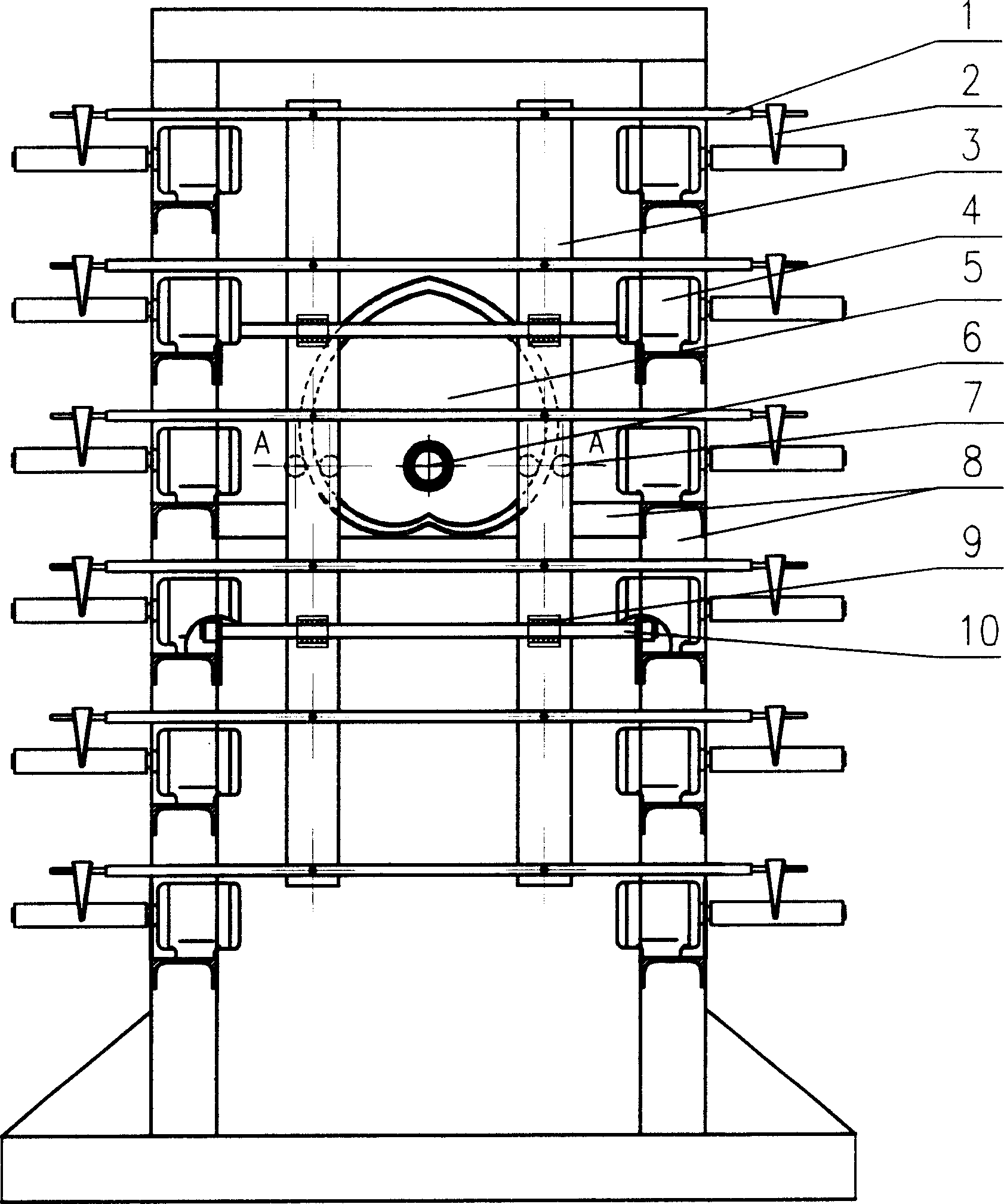
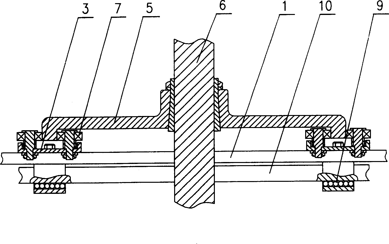
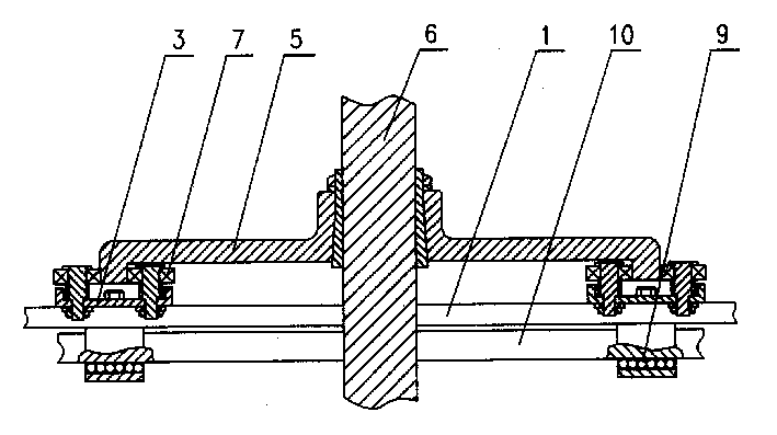
[0011] Refer to figure 1 , The whole machine is composed of a guide wire rod 1, a guide wire duckbill 2, a moving frame 3, a torque motor 4, a cam 5, a main shaft 6, a rolling bearing 7, a frame 8, a bearing 9, a guide shaft 10, etc. On both sides of the frame (8) are installed 4-6 layers of torque motors (4), the main shaft (6) is fixedly equipped with a cam (5), and the edge of the cam (5) has a rolling bearing (7) on both sides of the curved bosses on the left and right sides. ), the rolling bearing (7) is fixedly mounted on the left and right moving frames (3), and the moving frame (3) is additionally fixedly equipped with 4-6 layers of guide screw rods (1), and the two ends of the guide screw rods (1) are installed Guide wire duckbill (2). A bearing (9) is fixed on the moving frame (3), and the bearing (9) is in rolling fit with the guide shaft (10). The two ends of the guide shaft (10) are fixedly mounted on the frame (8). The cam (5) is a heart-shaped cam.

[0012] Refer t...


PUM


Abstract

The present invention relates to a cam type plastic flat yarn rolling-up machine, in particular, it is a flat yarn rolling-up machine for plastic wire-drawing operation. It is characterized by that on the structure of original flat yarn rolling-up machine the cam can be made into a boss whose edge has curve, the rolling bearings respectively fixedly mounted on left and right moving frames can be rolling fit with said curve boss, and the left and right two boss edges are respectively equipped with one rolling bearing. The described bearing is linear rolling bearing. Said invention can make the reciprocating movement and reversing motion of moving frame more stable and smooth, and can greatly raise flat yarn rolling-up quality.

Description

Technical field [0001] The invention relates to a flat yarn winding machine for plastic wire drawing, in particular to a cam type plastic flat yarn winding machine with a reciprocating winding mechanism. Background technique [0002] At present, the flat yarn winders for plastic wire drawing produced, sold and used at home and abroad use reciprocating screw mechanism to wind into spindles. Its structure is to use sliders to force friction and slide in the spiral grooves of the reciprocating screws to complete the flattening. The action of reciprocating wire winding into a spindle; this mechanism has the following defects: the slider in the spiral groove runs by forced friction slider, so the wear of the slider and the spiral groove is quite serious, and in the spiral groove There must be a transition arc at the reversing position of the groove, forming an instant stop, not a true reciprocating constant velocity motion, so that the winding of the ingot has a slub shape and the two...

Claims


Application Information

Patent Timeline
Patent Type & Authority Applications(China)
IPC IPC(8): B65H54/30
Inventor 陈志淡
Owner 雁峰集团有限公司
Learn More