


Quick Research
Generate reliable direction feasibility study reports for your R&D in just a few steps.

Technical Q&A
Discover and master advanced knowledge NOW. Basics, ideas, possibilities, all at once.

Find Solutions
As an expert in R&D theories, this can generate solutions to your technical problems instantly.

Evaluate Feasibility
Analyze your overall solution with one click, know your potential R&D risks in advance.

Monitor Landscape
Get weekly tech updates, stay abreast of the latest tech innovations and key insights.
Waveform monitoring device and method for monitoring waveform
A monitoring device and waveform technology, applied in the direction of applying stable tension/pressure to test the strength of materials, etc., can solve the problems of not showing the reference waveform, not knowing the difference and change of unqualified parts and unqualified degrees, and reduce the burden Effect
- Summary
- Abstract
- Description
- Claims
- Application Information
AI Technical Summary
Problems solved by technology
Method used
Image

Examples
Embodiment Construction
[0044] Embodiments of the simple waveform monitoring device according to the present invention will be described in detail with reference to accompanying drawings 1-3.
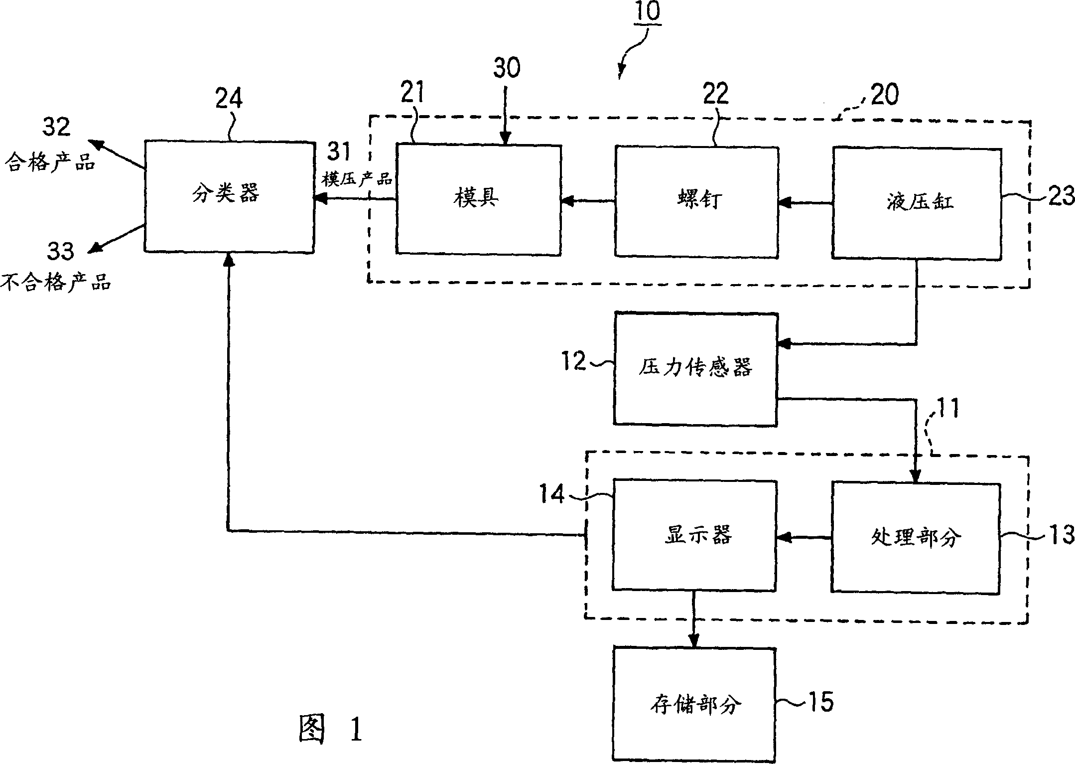
[0045] As shown in FIG. 1 , a simple waveform monitoring device 10 according to an embodiment of the present invention is combined with an injection molding tool 20 including a mold 21 , screws 22 , and a hydraulic cylinder 23 , and a classifier 24 . The simple waveform monitoring device 10 generally includes a pressure sensor 12 , a determination unit 11 and a storage portion 15 , wherein the determination unit 11 includes a processing portion 13 and a display 14 .
[0046] In the injection molding process, after the material (molding material) 30 is filled in the hydraulic cylinder (heating cylinder) 23, the injection molding tool 20 is pushed towards the screw head (not shown) and the ring valve (not shown) via the rotation of the screw 22 shown), the screw 22 engages with the screw head.
[0047] Next, th...
PUM
 Abstract
Description
Claims
Application Information
 - R&D Engineer
- R&D Manager
- IP Professional
- Industry Leading Data Capabilities
- Powerful AI technology
- Patent DNA Extraction
Browse by: Latest US Patents, China's latest patents, Technical Efficacy Thesaurus, Application Domain, Technology Topic, Popular Technical Reports.
© 2024 PatSnap. All rights reserved.Legal|Privacy policy|Modern Slavery Act Transparency Statement|Sitemap|About US| Contact US: help@patsnap.com