Chemical Supply device and method thereof

A supply device and liquid medicine technology, applied to the surface coating liquid device, pump device, separation method, etc., can solve the problems of reduced discharge accuracy, unstable liquid medicine discharge, and poor quality

Inactive Publication Date: 2004-06-30
KOGANEI
View PDF1 Cites 33 Cited by
  • Summary
  • Abstract
  • Description
  • Claims
  • Application Information

AI Technical Summary

Problems solved by technology

[0004] When discharging chemical liquid such as photosensitive adhesive liquid, if air bubbles are mixed into the device, the air bubbles will absorb the pressure to force out the chemical liquid, thereby making the discharge amount of the chemical liquid unstable and reducing the discharge accuracy.
Therefore, semiconductor integrated circuits formed on semiconductor single wafers cannot be manufactured with high quality and high yield.

Method used


Image

  • Chemical Supply device and method thereof
  • Chemical Supply device and method thereof
  • Chemical Supply device and method thereof

Examples


Embodiment Construction

[0017] Hereinafter, embodiments of the present invention will be described in detail with reference to the drawings.

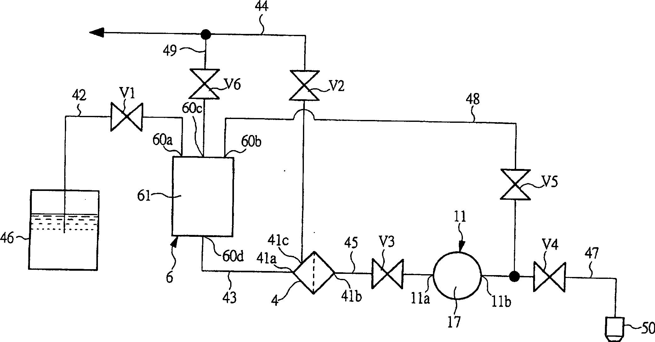
[0018] figure 1 It is a liquid circuit diagram showing the outline of a chemical liquid supply device as one embodiment of the present invention. Such as figure 1 As shown, the buffer tank part 6 of the liquid medicine supply device is provided with a liquid storage chamber 61 inside, and a liquid inflow port 60a connected to the liquid introduction flow path 42 is formed on the top wall, and a liquid inlet 60a connected to the return flow path 48 is formed. The inflow port 60b, the exhaust port 60c connected to the exhaust channel 49, and the liquid discharge port 60d connected to the communication channel 43 are formed on the bottom wall.

[0019] On the liquid inlet 60a of the buffer tank part 6, one end of the liquid introduction flow path 42 is connected. The liquid introduction flow path 42 is provided with an introduction valve V1 for opening and clos...


PUM


Abstract

A buffer tank section (6) includes a liquid accumulation chamber (61) communicating with, through a liquid introduction flow path (42), a liquid tank (46) accumulation chemical liquid. A filter section (4) includes a filter inlet (41a) and a filter outlet (41b), wherein the filter inlet (41a) communicates with a liquid discharge vent (60d) of the buffer tank section (6). In a pump (11), a pump inlet (11a) is connected to the filter outlet (41b) and a pump outlet (11b) is connected to a discharge nozzle (50) through a liquid discharge flow path (47). A return flow path (48) is connected between the pump outlet (11b) and the buffer tank section (6), wherein the chemical liquid, discharged from the pump (11), is returned to the liquid accumulation chamber (61). An exhaust flow path (49) is connected to the buffer tank section (6), thereby exhausting air in the liquid accumulation chamber (61).

Description

technical field [0001] The present invention relates to a chemical solution supply device and a chemical solution supply method for discharging a liquid such as a chemical solution in a predetermined amount, for example, to a suitable chemical solution supply device and a chemical solution used for coating a photosensitive adhesive on the surface of a semiconductor wafer. liquid supply method. technical background [0002] In manufacturing processes in various technical fields including semiconductor single wafer manufacturing technology, liquid crystal substrate manufacturing technology, magnetic disk manufacturing technology, and multilayer wiring substrate manufacturing technology, photoresist liquid, spin-on glass liquid ( Spinyongaras liquid), polyimide resin liquid, pure water, corrosive liquid, organic solvent and other chemical liquids, when applying these chemical liquids, use a chemical liquid supply device. [0003] For example, on the surface of a semiconductor ...

Claims


Application Information

Patent Timeline
Patent Type & Authority Applications(China)
IPC IPC(8): F04B23/02B01D19/00B05C11/10F04B53/06G03F7/16H01L21/00H01L21/027
CPCB01D19/0068H01L21/6715G03F7/16H01L21/027
Inventor 矢岛丈夫
Owner KOGANEI
Why Eureka
Try Eureka