Method for producing rubber drum

A technology of rubber roller and manufacturing method, which is applied in the direction of manufacturing tools, machine tools designed for grinding the rotating surface of workpieces, grinding machines, etc., which can solve the problems of large shaft core load, poor grinding accuracy, and damage to shape accuracy, so as to improve production Efficiency, excellent grinding accuracy, and shortened grinding time

Inactive Publication Date: 2004-06-30
SUMITOMO RUBBER IND LTD
View PDF1 Cites 4 Cited by
  • Summary
  • Abstract
  • Description
  • Claims
  • Application Information

AI Technical Summary

Problems solved by technology

However, in this infeed grinding, since the load on the shaft core is large, the problem of poor grinding accuracy such as deflection of the rubber roller and loss of shape accuracy such as flatness and cylindricity tends to occur during grinding.

Method used


Image

  • Method for producing rubber drum
  • Method for producing rubber drum
  • Method for producing rubber drum

Examples


Embodiment

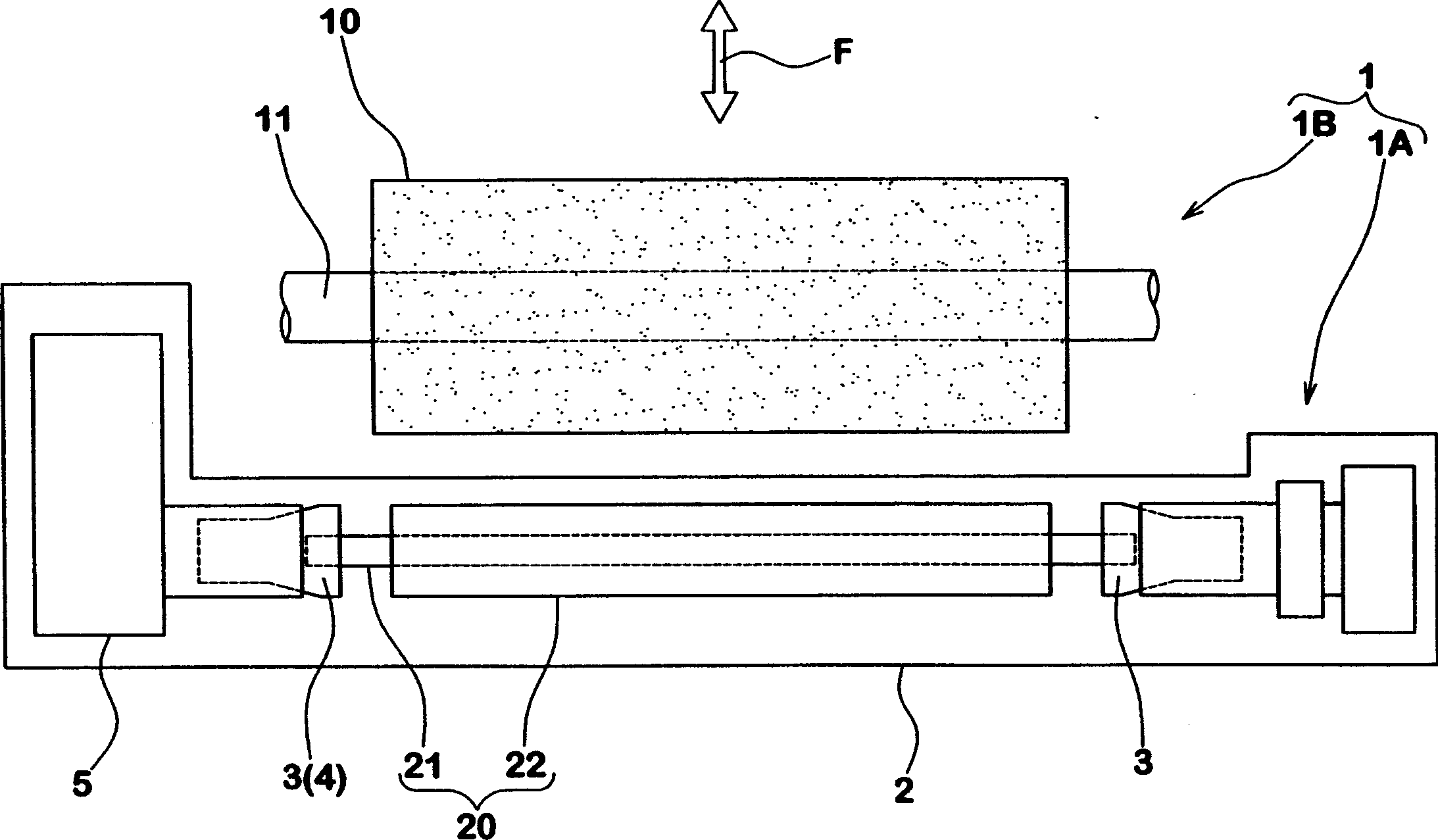
[0055] According to the grinding step S of the present invention, on the basis of the following conditions, the rubber cylinder with length L (240mm) and diameter D (18mm) is rotated at a rotational speed of 150rpm, and is ground with a grinding tool at the same time, and the measurement process becomes the surface Grinding time for products with a diameter of (15) mm.

[0056] Abrasives

[0057] ·Width: 260mm

[0058] ·Fineness: 80 mesh

[0059] ·Rotation speed: 2000rpm

[0060] Grinding step (no vibration)

[0061] · Preparatory grinding steps

[0062] Forward speed V1: 21mm / min

[0063] Grinding time T1: 3 seconds

[0064] ·Intermediate grinding step

[0065] Forward speed V2: 17mm / min

[0066] Grinding time T2: 3 seconds

[0067] ·Finish grinding step

[0068] Forward speed V3: 1mm / min

[0069] Grinding time T3: 12 seconds

[0070] · Non-spark grinding steps

[0071] Forward speed V4: 0mm / min

[0072] Grinding time T4: 5 seconds

[0073] In contrast, on the ...


PUM


Abstract

To shorten grinding time while exhibiting superior grinding accuracy. A rubber part 22 of a rubber roller is ground by the following grinding steps S of using a grinding wheel 10 wider than the length. The grinding steps S include a preliminary grinding step S1 for grinding by pushing the grinding wheel 10 at a first advance speed V1 of 15 to 25 mm / min toward the axis of the rubber roller 20, an intermediate grinding step S2 for grinding by pushing the grinding wheel at a second advance speed V2 lower than that speed, a finishing grinding step S3 for grinding by pushing the grinding wheel at a third advance speed V3 further lower than that speed and a sparkless grinding step S4 for holding the advance movement in a state of stopping in the final position P of the finishing grinding step S3. (C)2004,JPO&NCIPI.

Description

technical field [0001] The present invention relates to a method for manufacturing a rubber roller; more specifically, the present invention relates to a method for manufacturing a rubber roller that can be processed efficiently by grinding while maintaining a predetermined outer diameter with high precision. Background technique [0002] In copiers, facsimile machines, and printers, for transmitting paper, such as Image 6 A rubber roller c with a rubber portion b mounted around the shaft core a is shown. Moreover, when manufacturing such a rubber roller c, in general, in order to process the vulcanized rubber roller c1 with a shaft core to a predetermined outer diameter, it is necessary to grind the above-mentioned rubber portion b. [0003] However, the conventional grinding process is as Image 6 As shown, the so-called longitudinal feed grinding is used, that is, the abrasive tool e with a narrow width is in contact with the outer peripher...

Claims


Application Information

Patent Timeline
Patent Type & Authority Applications(China)
IPC IPC(8): B24B5/50B24B5/37B24D5/00
Inventor 张亚军藪下俊一
Owner SUMITOMO RUBBER IND LTD
Why Eureka
Try Eureka