
High fidelity audio signal amplifying method

An audio signal and radio frequency signal technology, applied in the direction of amplification control, tone control, electrical components, etc., can solve the problems of complex electrical signals, unsatisfactory sound effects, and inferior analog amplifiers, etc., to achieve fast response and reduce distortion , the effect of low noise

Inactive Publication Date: 2004-04-14
余小宁
View PDF0 Cites 5 Cited by
  • Summary
  • Abstract
  • Description
  • Claims
  • Application Information

AI Technical Summary

Problems solved by technology

Theoretically, this type of amplifier can obtain a perfect amplification effect, but due to the influence of various complex factors, its actual sound effect is not satisfactory at present, even worse than some analog amplifiers
Although the frequency range of sound waves that can be detected by the human ear is only 20-20000Hz, the actual electrical signals obtained by the sound waves of music and speech through the sound-to-electricity conversion system are extremely complex, not a single simple harmonic. Fourier transform We know that the frequency spectrum of the audio signal of music and language is very wide, far beyond the range of 20-20000Hz

Method used

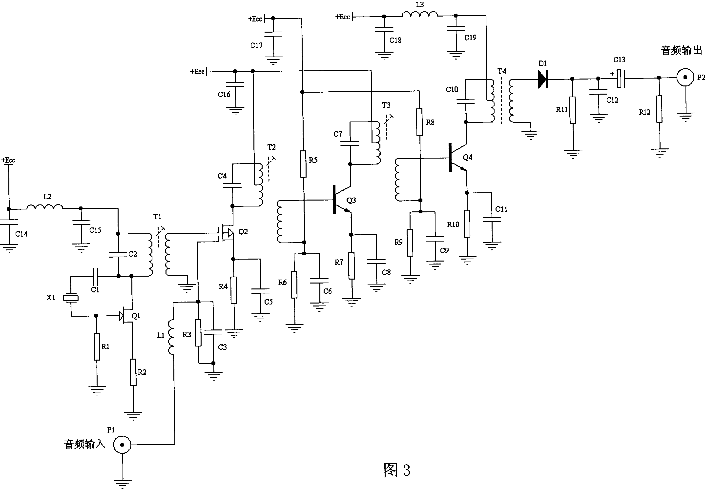

Image

  • High fidelity audio signal amplifying method
  • High fidelity audio signal amplifying method
  • High fidelity audio signal amplifying method

Examples


Embodiment Construction

[0016] Describe in detail below in conjunction with accompanying drawing.

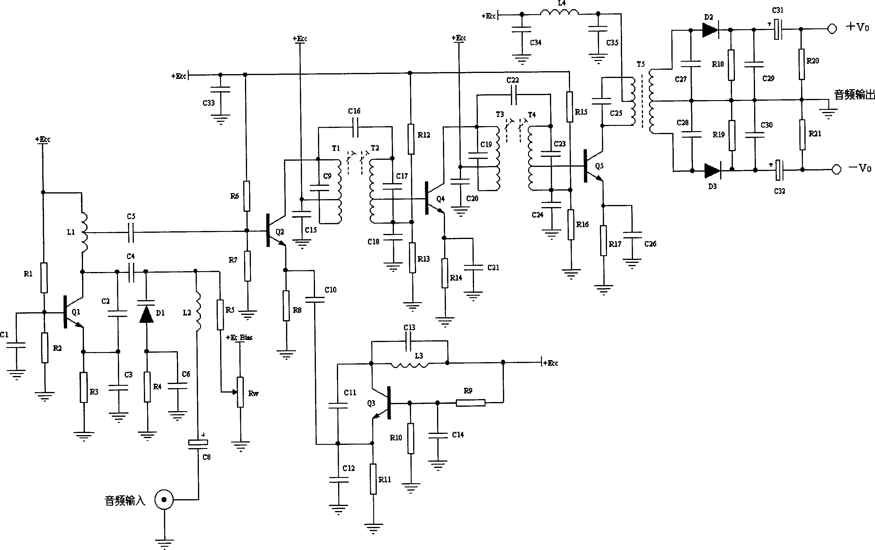
[0017] figure 2 For the audio frequency preamplifier circuit schematic diagram of the FM mode work designed according to the principles of the present invention, figure 2 Among them, Q1, Q2, Q3 and peripheral components constitute a frequency modulator, among which Q1 and peripheral components constitute a VHF oscillation signal source and a frequency modulator, and the audio signal is directly added to the varactor diode D1, so that the capacitance of D1 changes with the audio signal so that Change the oscillation frequency of the oscillator. The frequency modulation signal is added to the frequency conversion circuit composed of Q2 and Q3 through C5 to convert the very high frequency signal into a lower frequency intermediate frequency signal, Q3 is the local oscillator signal source, and Q2 is the mixer. After the intermediate frequency signal is amplified by the two-stage high-frequency amplifi...


PUM


Abstract

Modulating certain parameter (such as frequency, phase or amplitude) of radio frequency signal for sound signal to be magnified obtains a radio frequency signal carrying information of sound signal to be magnified. Using high frequency amplifier magnifies the radio frequency signal, and then demodulating the magnified radio frequency signal restores sound signal. When high-frequency signal is magnified, the sound signal is also magnified indirectly.

Description

Technical field: [0001] The invention relates to audio signal amplification technology. In particular, a high-fidelity audio signal amplification method based on radio frequency transmission and a corresponding audio signal amplifier. Background technique: [0002] In the field of high-fidelity audio amplifiers, the existing audio signal amplification modes all adopt the basic form of broadband linear direct analog amplification. Although there are many forms of amplifiers, such as feedback amplification, feedforward amplification (also known as current pouring), pre-distortion amplification correction, etc.; and the working status of the amplifier is different, there are A class, AB class, B class Classes, etc.; the structure of the amplifier is different, there are single-ended, PP (symmetrical push-pull) type, SEPP (single-ended push-pull) type, and SRPP, etc.; the components used are different, there are vacuum tube amplifiers, bipolar transistor amplifiers, Field effe...

Claims


Application Information

Patent Timeline
Patent Type & Authority Applications(China)
IPC IPC(8): H03G5/00H03G9/00
Inventor 余小宁
Owner 余小宁
Learn More