Filter with hole in its filtering part

A filter and inlet part technology, applied in the field of fuel injection devices, can solve problems such as increased pressure loss

Active Publication Date: 2004-03-10
DENSO CORP
View PDF0 Cites 11 Cited by
  • Summary
  • Abstract
  • Description
  • Claims
  • Application Information

AI Technical Summary

Problems solved by technology

On the other hand, if the gap is reduced to increase the trapping performance, the pressure loss due to the reduced flow area will again increase

Method used


Image

  • Filter with hole in its filtering part
  • Filter with hole in its filtering part
  • Filter with hole in its filtering part

Examples


Embodiment Construction

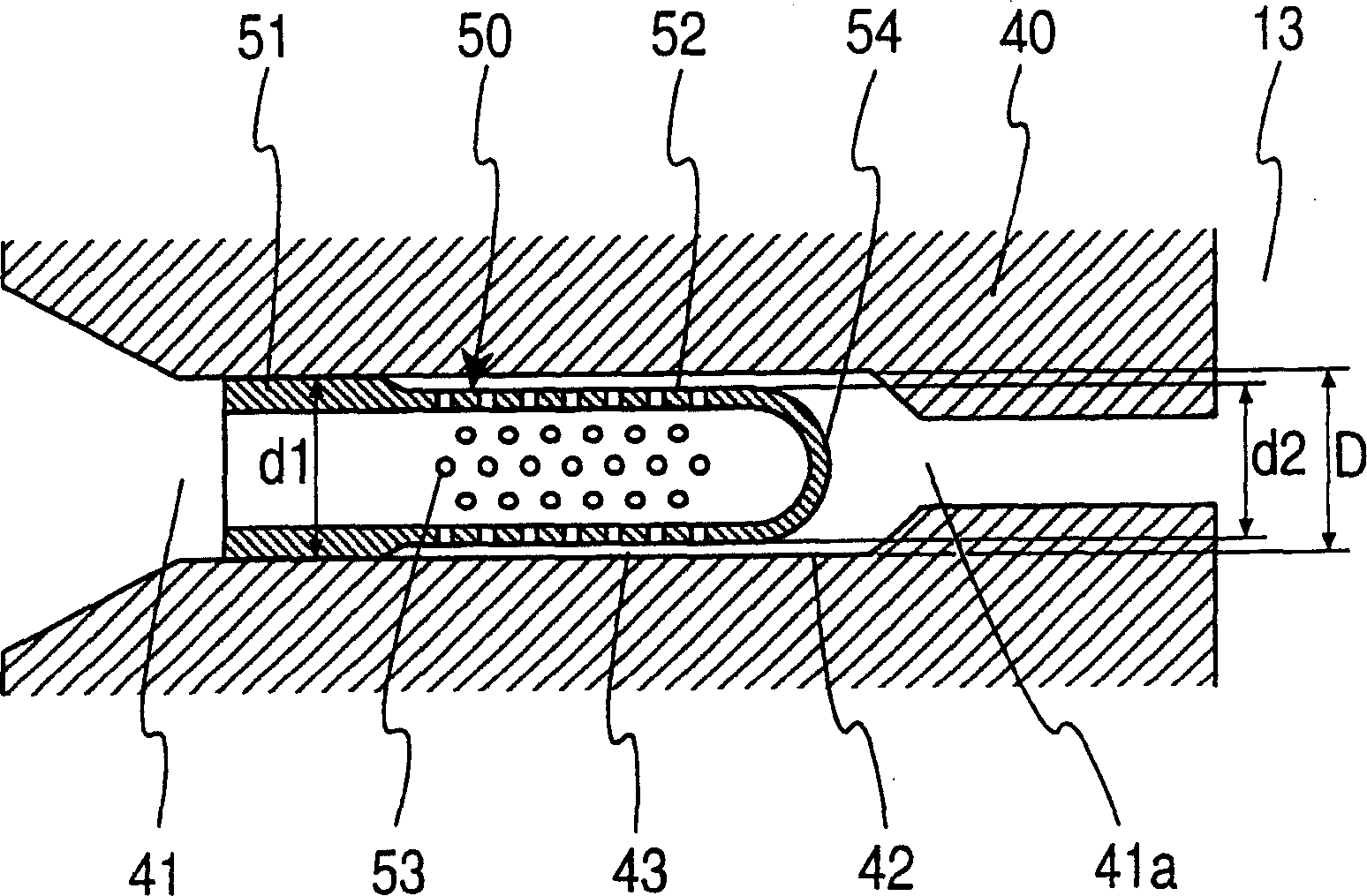
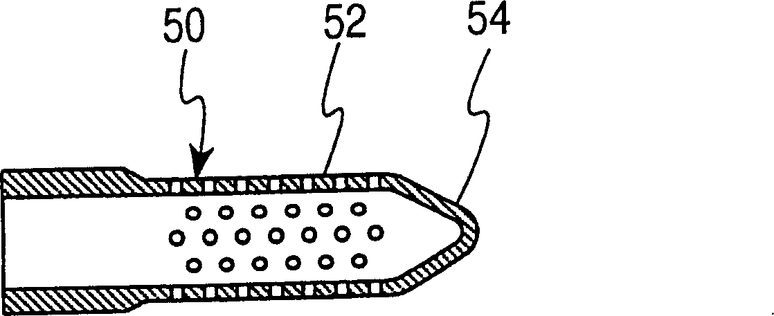
[0023] refer to figure 1 , a filter of the present invention is indicated by reference numeral 50 and applied to a fuel injector 1 used in a common rail fuel injection system of a diesel engine. The injector 1 includes a body portion 10 having a housing 11 , a nozzle portion 20 and an electromagnetic drive portion 30 . The injector 1 is arranged on a cylinder head of an engine, and is used for introducing fuel into corresponding cylinders.

[0024] The housing 11 is substantially cylindrical, and a fuel introduction port 40 protrudes from the outer peripheral surface of the housing 11 in a side direction and is integrally formed as a fuel introduction passage body. A fuel introduction passage 41 is formed in the fuel introduction port 40, and a filter 50 is provided in the fuel introduction passage. The fuel introduction port 40 is connected to a common rail (not shown).

[0025] In the nozzle portion 20, a retainer 24 is fixed to the bottom end of the casing 11, and an end...


PUM


Abstract

A filter is press-inserted into a mounting bore of an injector. The filter has an inlet section at an opening-end fuel inlet side and a filter section which has a number of holes. The bottom of the filter section is hemispherically-shaped so that a flow area formed between the outer surface of the hemispherical bottom portion and the inner round surface of the mounting inlet bore widens gradually to reduce pressure loss effectively.

Description

technical field [0001] The present invention relates to a filter provided in a fluid passage for trapping foreign matter contained in a fluid, and to a fuel injection device applied to an internal combustion engine and using the filter. Background technique [0002] In recent years, in order to comply with diesel engine emission regulations, diesel engine fuel is subjected to high pressure, and electronic control systems are also applied to injection systems. Regarding fuel injection devices, conventional automatic valve control systems have been replaced by electronically controlled nozzle systems with solenoid valves. Filters for trapping foreign matter in fuel to protect fuel injectors also have increased requirements, such as a precise sliding portion, a solenoid valve, and a nozzle. Filters fall broadly into two categories. One type is used to capture normal foreign matter in the oil. Another type is used to capture foreign matter generated during the processing of p...

Claims


Application Information

Patent Timeline
IPC IPC(8): B01D29/11B01D29/35B01D35/02F02M37/22F02M47/02F02M59/46F02M61/16
CPCB01D29/35F02M2200/04F02M47/027B01D35/02F02M61/165F02M37/22B01D2201/184F02M37/32
Inventor 山口隆依田稔之伊藤荣次东条千太
Owner DENSO CORP
Why Eureka
Try Eureka