Camera and camera element unit

An imaging element and camera technology, applied in the field of cameras, can solve problems such as the enlargement of the camera, and achieve the effects of suppressing the enlargement, simplifying the manufacturing process, and stabilizing the accuracy of the mechanism

Inactive Publication Date: 2003-12-10
OM DIGITAL SOLUTIONS CORP
View PDF3 Cites 12 Cited by
  • Summary
  • Abstract
  • Description
  • Claims
  • Application Information

AI Technical Summary

Problems solved by technology

Therefore, there is a problem that the size of the camera itself is increased

Method used


Image

  • Camera and camera element unit
  • Camera and camera element unit
  • Camera and camera element unit

Examples


Embodiment Construction

[0129] First, a brief structure of the camera of the first embodiment of the present invention will be described below.

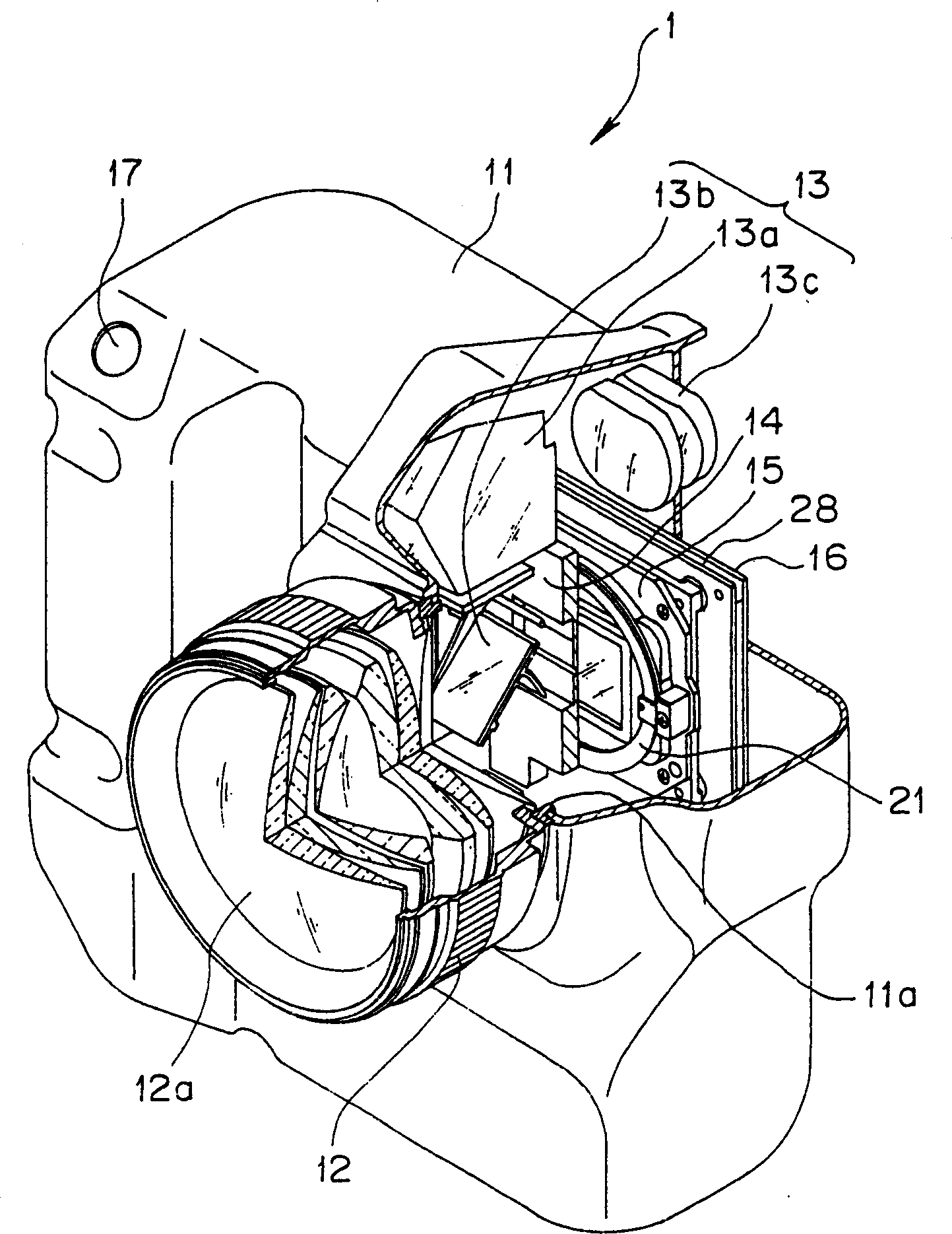
[0130] figure 1 , figure 2 is a diagram showing a schematic configuration of a camera according to a first embodiment of the present invention, figure 1 Indicates that a part of the camera is cut off, and a perspective view of its internal structure is briefly indicated, figure 2 is a structural block diagram briefly showing the main electrical structure of the camera.

[0131] The camera 1 of this embodiment is composed of a camera main body 11 and a lens barrel 12 which are separately constructed, and both (11, 12) are detachably detachable from each other.

[0132] The lens barrel 12 internally holds a photographing optical system (also referred to as photographing lens) 12 a composed of a plurality of lenses and the like, a driving mechanism thereof, and the like. This imaging optical system 12a is constituted by, for example, a plurality of optic...


PUM


Abstract

Camera and camera element unit are provided in the invention. The camera includes an image pick-up device which obtains an image signal corresponding to beams irradiated onto a photoelectrically converting surface thereof; a dust-proofing member with a circular or polygonal plate-shape as a whole, including a transparent portion at an area having at least a predetermined extensity in a radial direction from the center thereof, opposed to the front of the optical device at a predetermined interval; a member for vibration annularly arranged at a peripheral portion of the dust-proofing member, which applies vibrations to the dust-proofing member; a sealing structure arranged to constitute a space portion that is substantially sealed at a portion formed by opposing the image pick-up device and the dust-proofing member by sealing the space portion at peripheral portions of the image pick-up device and the dust-proofing member; and an image signal processing circuit which converts an image signal obtained from the image pick-up device, corresponding to an image formed onto the photoelectrically converting surface of the image pick-up device, into a signal suitable to recording.

Description

technical field [0001] The present invention relates to an imaging element unit having an imaging element that obtains an image signal corresponding to light irradiated on its photoelectric conversion surface, and a camera having the imaging element unit, and more specifically, to a single-lens reflex type digital camera with an interchangeable imaging lens. A camera, etc., a camera having a dust-proof structure of an imaging element, and an imaging element unit used in the camera. Background technique [0002] In recent years, digital cameras such as so-called digital still cameras and digital video cameras (hereinafter simply referred to as digital cameras or still cameras) have been put into practical use and widely popularized. (also called a photographic lens) The object image formed by the light beam of the object (hereinafter referred to as the object light beam) is placed on a solid-state imaging device at a predetermined position, such as a charge-coupled device (CC...

Claims


Application Information

Patent Timeline
Patent Type & Authority Applications(China)
IPC IPC(8): G03B17/02G03B19/02H04N5/225
CPCH04N5/2254H04N23/52H04N23/55H04N23/65H04N23/63H04N23/811
Inventor 滝沢宏行川合澄夫
Owner OM DIGITAL SOLUTIONS CORP
Why Eureka
Try Eureka