Method of forming embolism and hole

A plug hole and spin-on glass technology, which is applied in the direction of electrical components, semiconductor/solid-state device manufacturing, circuits, etc., can solve problems such as difficulty, high aspect ratio, and lower quality of metal lines, so as to reduce the difficulty and thickness of filling Effect of reducing and increasing process tolerance

Inactive Publication Date: 2003-11-05
MACRONIX INT CO LTD
View PDF0 Cites 0 Cited by
  • Summary
  • Abstract
  • Description
  • Claims
  • Application Information

AI Technical Summary

Problems solved by technology

[0007] The side hole 190 formed due to misalignment will cause the metal aluminum in the metal stack layer to be etched out, and the aspect ratio of the two will be very large, which will cause difficulties for the subsequent filling of the TiN layer. Therefore, Causes the final resistance to rise, reducing the quality of the metal line

Method used


Image

  • Method of forming embolism and hole
  • Method of forming embolism and hole
  • Method of forming embolism and hole

Examples


Embodiment Construction

[0021] The present invention provides a kind of technological method that solves the hollow phenomenon in plugging hole etching, replaces traditional SiON layer with a spin-on-glass layer (SOG, spin on glass) or dyed spin-on-glass layer (dyed SOG), not only The un-landed phenomenon when etching the vias can be avoided, and the spin-on-glass layer or dye spin-on-glass layer also has the function of a hard mask layer, so the thickness of the photoresist layer can be reduced.

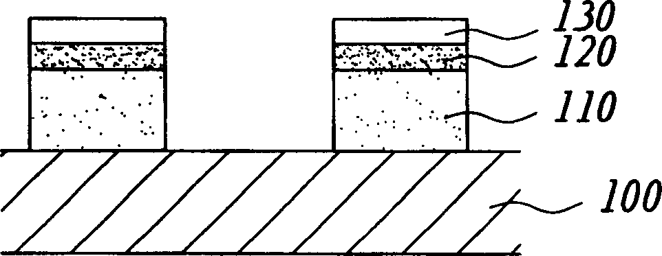
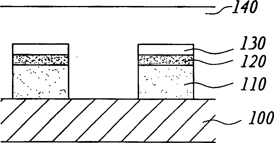
[0022] Figure 5 Shown is a cross-sectional view of a semiconductor showing the formation of metal stack layers according to the present invention. First, a substrate 500 is provided, and a metal layer 510 and an anti-oxidation reflective layer 520 are sequentially deposited on the substrate 500 by PVD deposition method, wherein the metal layer 510 is usually an aluminum layer, and the anti-oxidation reflective layer 520 is typically a TiN layer. Next, a spin-on-glass layer 535 is formed on the anti-oxid...


PUM

PropertyMeasurementUnit
thicknessaaaaaaaaaa

Abstract

The present invention discloses one manufacture process capable of avoiding un-landed phenomenon caused by error aligning. The process includes providing one substrate with formed metal layer and anti-reflecting layer; forming one spin-on glass layer on the anti-reflecting layer; defining several metal wires produced through etching the metal layer, the anti-reflecting layer and the spin-on glass layer; depositing oxide layer on the substrate to cover the metal wires; and defining several embolism hole via etching the oxide layer. The spin-on glass layer may be replaced with one dye spin-onglass layer, and in this case the step of forming anti-reflecting layer may be omitted.

Description

technical field [0001] The invention relates to a manufacturing method of a circuit board, in particular to a manufacturing method for forming plugging holes of the circuit board, which can effectively solve the hollowing phenomenon. Background technique [0002] In the semiconductor manufacturing process where the line width is continuously shrinking, some phenomena that do not pose a problem when the line width is large will gradually pose a threat to the manufacturing yield in sub-micron manufacturing, such as in the via etching step. The hollow (un-landed) phenomenon produced by misalignment. [0003] Figure 1 to Figure 4 Shown is the formation process of the plug in the conventional technology. like figure 1 Shown is the situation where a metal stack layer is formed on a substrate 100. First, a metal aluminum layer 110 is formed on the substrate 100 by PVD deposition, and then, the same is deposited on the metal aluminum layer 110 by PVD. , forming a TiN layer 120,...

Claims


Application Information

Patent Timeline
Patent Type & Authority Applications(China)
IPC IPC(8): H01L21/28H01L21/30H01L21/768
Inventor 郑培仁
Owner MACRONIX INT CO LTD
Why Eureka
Try Eureka