High-frequency multiple-pulse ultrasonic emission driver and receiving circuit

A technology of transmitting drive and receiving circuit, which is applied in the field of high-frequency multi-pulse ultrasonic transmitting drive and pre-signal receiving circuit, which can solve the problems of poor instrument performance and precision, easy to be interfered, etc., and achieve good inhomogeneity and simple circuit Reliable, low-latency effects

Inactive Publication Date: 2003-11-05
王京先
View PDF0 Cites 9 Cited by
  • Summary
  • Abstract
  • Description
  • Claims
  • Application Information

AI Technical Summary

Problems solved by technology

The ultrasonic transmitting sensor of this ultrasonic flowmeter --- piezoelectric ceramic sheet, which belongs to capacitive load --- needs a large peak current high-frequency pulse drive signal to minimize the delay time of the circuit and improve the measurement accuracy of the instrument ; On the other hand, the original receiving signal induced by the receiving sensor is very small, and it is easily interfered in industrial applications, which makes the performance and accuracy of the instrument worse

Method used


Image

  • High-frequency multiple-pulse ultrasonic emission driver and receiving circuit
  • High-frequency multiple-pulse ultrasonic emission driver and receiving circuit

Examples


Embodiment Construction

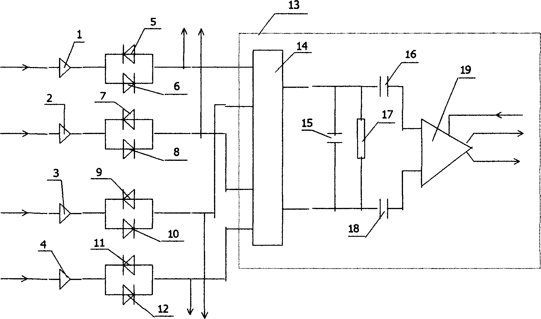
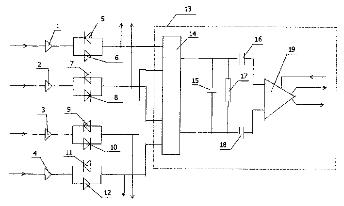
[0012] Below in conjunction with accompanying drawing and embodiment the utility model is further described.

[0013] The current drivers 1, 2, 3, and 4 are TC4424 dual-channel MOSFET integrated drivers produced by the American MICROCHIP company, and the diodes 5, 6, 7, 8, 9, 10, 11, and 12 of the four groups of positive and negative diode pairs connected in parallel The conventional switching diode 1N4148 is selected, the integrated analog switch 14 is selected from the MAX4632 produced by MAXIM Company of the United States, and the automatic gain control amplifier 19 with dual balanced input uses the M1350 produced by Motorola. Capacitors 15, 16, 18 are 0.01uF, and resistor 17 is 1000 ohms.

[0014] The existing high-current MOSFET driver integrated circuit block is used to directly generate a large peak current drive signal, which is coupled to a piezoelectric ceramic chip through a switch diode with positive and negative poles connected in parallel for driving. The positi...


PUM

PropertyMeasurementUnit
Capacitanceaaaaaaaaaa

Abstract

The present invention belongs to the field of linear electronic circuit technology. The high-frequency multiple-pulse ultrasonic emission driver and receiver circuit includes receiving pre-amplifiers, four oppositely connected diode pairs, each of which is connected between one of four current drivers and one of four receiving pre-amplifiers, each of which consists of analogue switch, low-pass RC filter, coupling capacitors, and variable-gain high-frequency amplifier. The present invention can produce high-frequency differential current driving signal for the piezoelectric ceramic chip as the sensor of ultrasonic flowmeter in less delay and small drift and the receiver circuit has high anti-jamming performance.

Description

technical field [0001] The invention relates to a high-frequency multi-pulse ultrasonic transmitting drive and pre-signal receiving circuit used in an ultrasonic flowmeter. Background technique [0002] Time-difference ultrasonic flowmeter is a velocity-type flowmeter that converts the flow velocity of the fluid by detecting the transit time difference of the upper and lower ultrasonic signals passing through the fluid in the pipeline, hereinafter referred to as time difference. The ultrasonic transmitting sensor of this ultrasonic flowmeter --- piezoelectric ceramic sheet, which belongs to capacitive load --- needs a large peak current high-frequency pulse drive signal to minimize the delay time of the circuit and improve the measurement accuracy of the instrument ; On the other hand, the original receiving signal induced by the receiving sensor is very small, and it is easily interfered in industrial applications, which makes the performance and accuracy of the instrument ...

Claims


Application Information

Patent Timeline
IPC IPC(8): G01F1/66
Inventor 王京先
Owner 王京先
Why Eureka
Try Eureka