
Multi-path dynamic routing algorithm

A path and routing technology, which is applied in the direction of data exchange, calculation, computer, etc. through path configuration, and can solve problems such as congestion

Inactive Publication Date: 2003-10-15
INTEL CORP
View PDF0 Cites 10 Cited by
  • Summary
  • Abstract
  • Description
  • Claims
  • Application Information

AI Technical Summary

Problems solved by technology

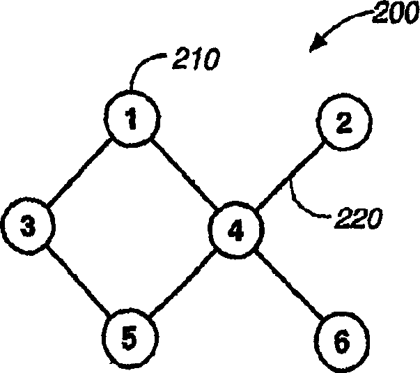
As a result, if node 1 wants to send a stream to node 5 at 40 Mbps, the path through node 4 is an attractive one, but the path is actually congested at node 4

Method used


Image

  • Multi-path dynamic routing algorithm
  • Multi-path dynamic routing algorithm
  • Multi-path dynamic routing algorithm

Examples


Embodiment Construction

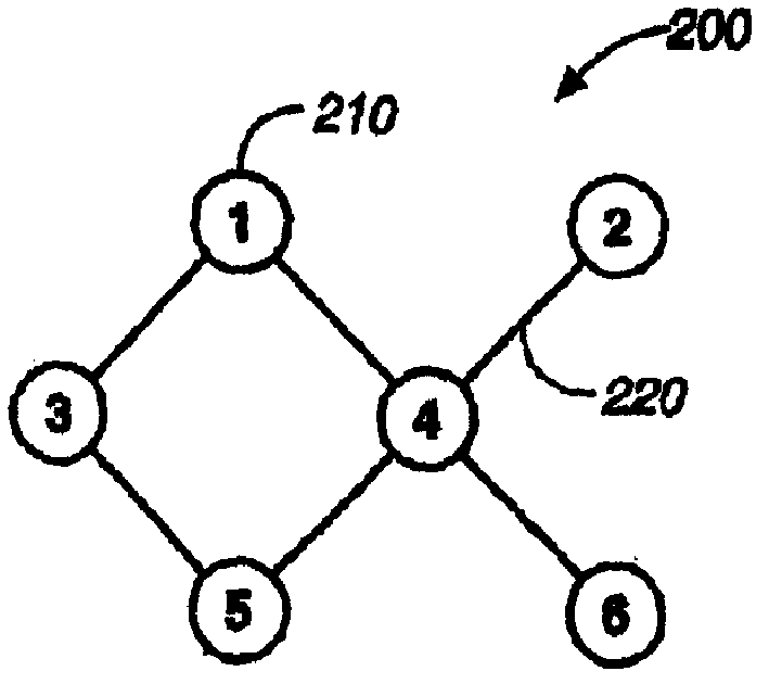
[0013] refer to figure 2 , compute the metric of the path from node 1 to node 5 via node 4 by summing the node metrics of all intermediate nodes. Here, node 4 is the only intermediate node on the path, so its metric is also the path metric of the path. Other methods for combining node metrics of intermediate nodes on a path can also be used to compute the path metric.

[0014] The node bandwidth of a node 210 is the maximum processing rate of a node 210 in the network 200 . Since a node 210 can only communicate with one other node 210 at any one time, the bandwidth of a node 210 is shared by all of its links. Assuming node 4 has a bandwidth of 100 Mbps, then this bandwidth can be shared among its four links to nodes 1, 2, 5 and 6. In other words, the sum of the data communication rates of the node 4 on these four links must be 100 Mbps or less. Generally speaking, let R(i, j) represent the communication rate on the link i-j, then R(4,1)+R(4,2)+R(4,5)+R(4,6)<= 100Mbps, whe...


PUM


Abstract

Disclosed is a routing algorithm that uses a new concept of node metric system for optimizing the throughput of a network, in particular, a shared medium network. The measure of congestion of a path in the network is represented by a path metric which is computed by summing the node metrics of the intermediate nodes on the path. Factors used in computing node metrics include the following: 1. future traffic load from neighboring nodes to the node; and 2. future traffic load from the node to the neighboring nodes.

Description

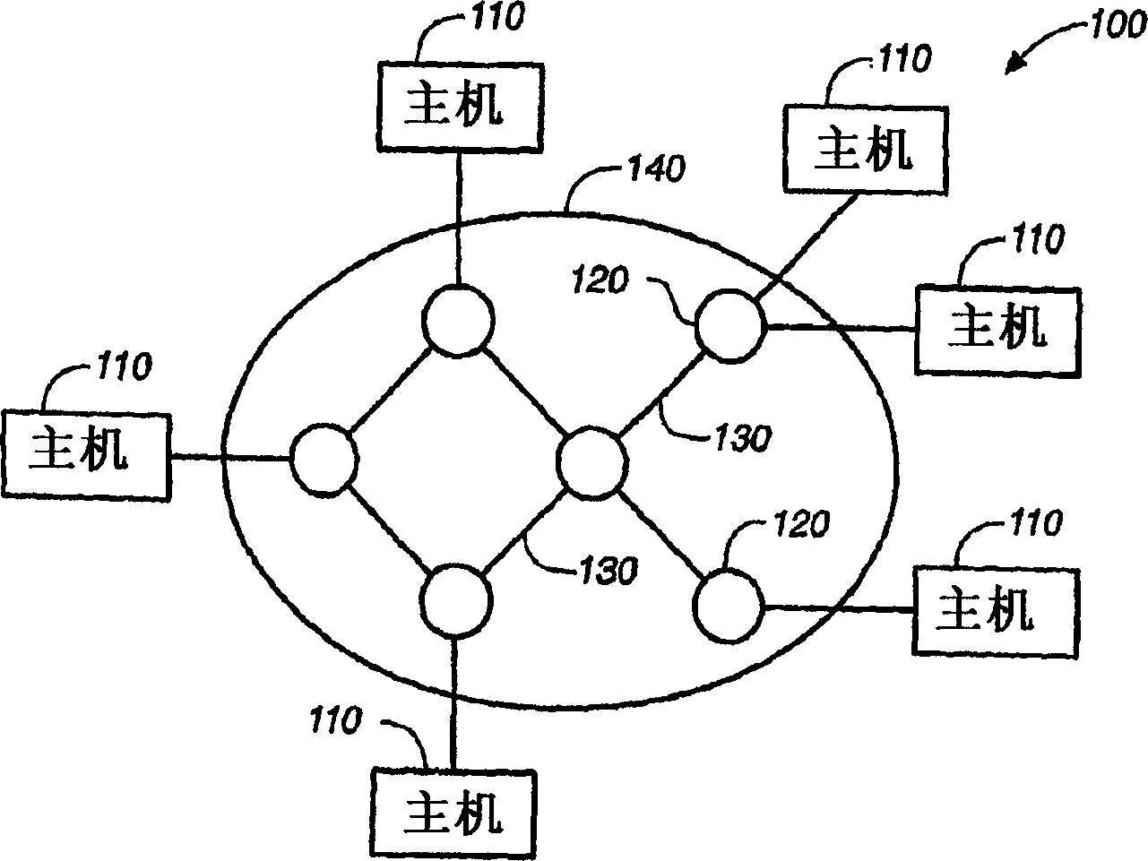
technical field [0001] The invention relates to a method for improving routing in a data network. In particular, the present invention discloses a method for routing data in a network where the processing speed of routers in the network is a limiting factor. technical background [0002] FIG. 1 shows the structure of a typical network 100 in the prior art. Network 100 includes a plurality of hosts 110 for running applications. Network 100 also includes a subnet 140 that connects hosts 110 and passes messages between them. Subnetwork 140 typically includes two basic components: routers 120 (also called switching elements, nodes, or interface message processors) and links 130 (also called transmission lines). Each host 110 is connected to one, or occasionally several routers 120 . [0003] A number that allows comparison of paths connecting the same pair of source-destination routers 120 is called a metric. A path consists of a set of links 130 connecting a pair of source...

Claims


Application Information

Patent Timeline
Patent Type & Authority Applications(China)
IPC IPC(8): H04L12/56
CPCH04L45/12H04L45/123
Inventor 帕特里克·A·沃佛克瑟格·普罗特肯施姆尔·拉维德拉宾诺维兹伊泰·阿隆逊
Owner INTEL CORP
Learn More