
Method for removing manganese in cast iron molten liquid and method for manufacturing nodular graphite cast iron

A manufacturing method and technology of ductile iron, applied in the field of manganese removal, can solve the problems of unclear Mn removal effect, increased production cost, complicated operation and management, etc.

Inactive Publication Date: 2003-10-15
ASAHI TEC CORP
View PDF1 Cites 4 Cited by
  • Summary
  • Abstract
  • Description
  • Claims
  • Application Information

AI Technical Summary

Problems solved by technology

In addition, the Mn content in the copper-containing molten liquid used as a raw material is a relatively low level of 0.53 to 0.61% by weight. For scrap steel containing a lot of Mn, mainly the above-mentioned high-strength steel sheets, the removal effect of Mn is unclear. A mixture of two additives (Na 2 S, Na 2 SO 4 ), resulting in complex operation and management, and increased production costs including additive costs

Method used


Image

  • Method for removing manganese in cast iron molten liquid and method for manufacturing nodular graphite cast iron
  • Method for removing manganese in cast iron molten liquid and method for manufacturing nodular graphite cast iron
  • Method for removing manganese in cast iron molten liquid and method for manufacturing nodular graphite cast iron

Examples


Embodiment 1~6

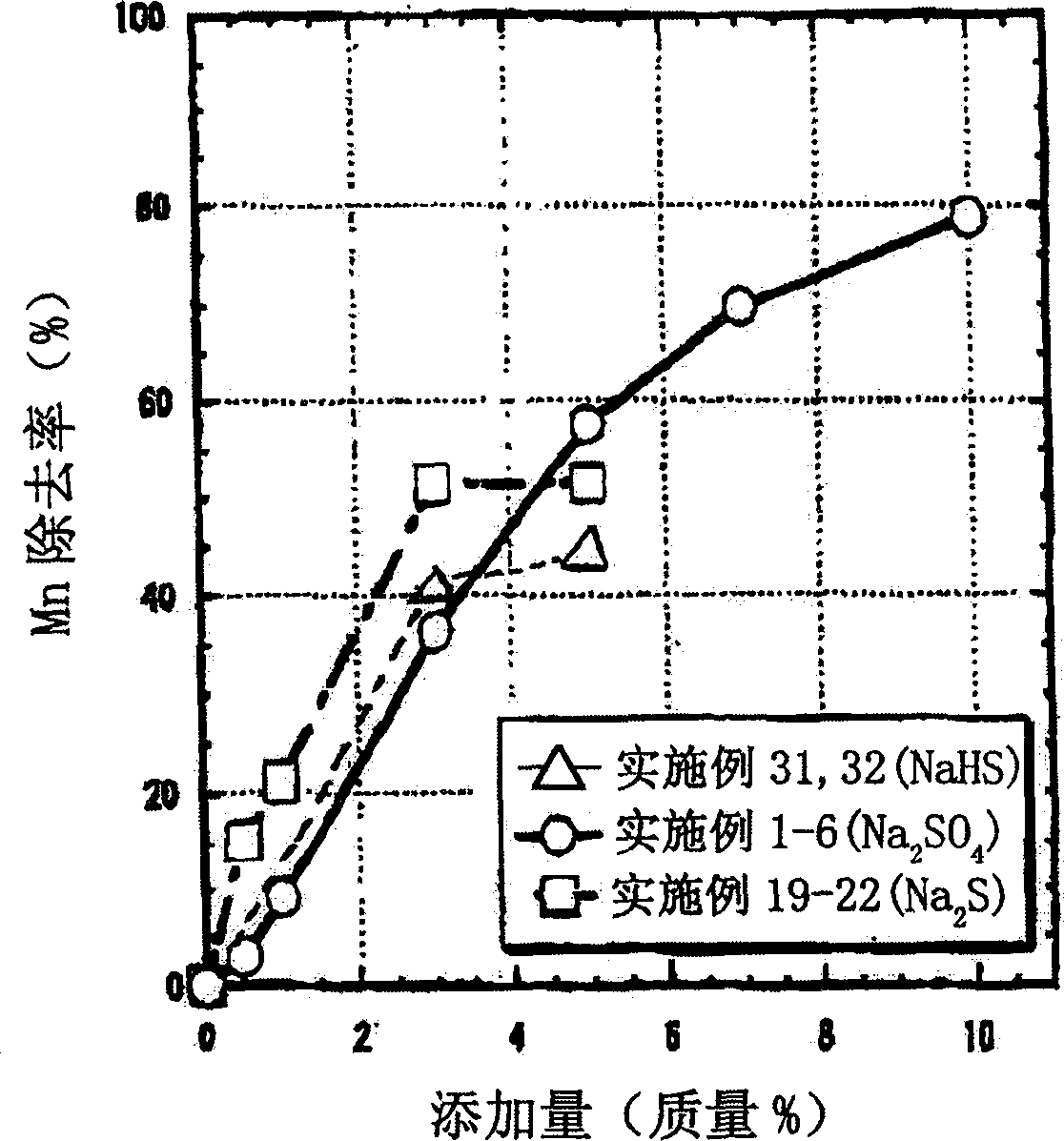
[0082] Using high-purity pig iron, electrolytic iron, and Fe-Mn alloy, a high-frequency electric furnace is used to smelt an intermediate alloy containing 0.35% by mass of Mn. Then, chemical analysis was performed to investigate the Mn content (mass %) in the master alloy (this Mn content is referred to as Mn1). Table 1 shows Mn and other chemical components (% by mass) of the master alloy.

[0083] master alloy

C

Si

mn

P

S

Mn0.35%

3.55

2.66

0.34

0.034

0.009

Mn0.7%

3.47

2.66

0.67

0.035

0.010

Mn1.5%

3.45

2.65

1.50

0.036

0.011

[0084] Next, 600 g of the master alloy was put into a graphite crucible with an inner diameter of 75 mmΦ×a height of 95 mm and melted in a high-frequency electric furnace. Then, while maintaining the temperature at 1400°C, add and mix Na 2 SO 4 As an additive, remove the slag after 5 minutes, ta...

Embodiment 7~12

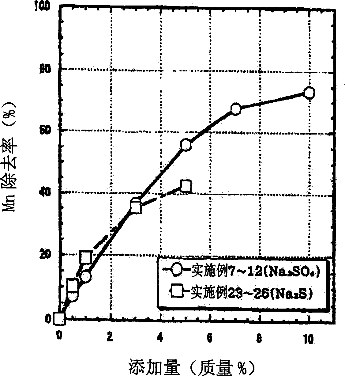
[0090] The Mn removal rate (%) was determined in the same manner as in Examples 1 to 6, except that a master alloy formulated to contain 0.7% by mass of Mn was used. Table 1 shows Mn and other chemical components (% by mass) of the master alloy. Na 2 SO 4 The addition amount is 0.5 mass % (embodiment 7), 1 mass % (embodiment 8), 3 mass % (embodiment 9), 5 mass % (embodiment 10), 7 mass % (embodiment 11), 10 mass % Mass % (Example 12). figure 2 shows the Na according to Examples 7-12 2 SO 4 The relationship between the amount of addition and the removal rate of Mn.

Embodiment 13~18

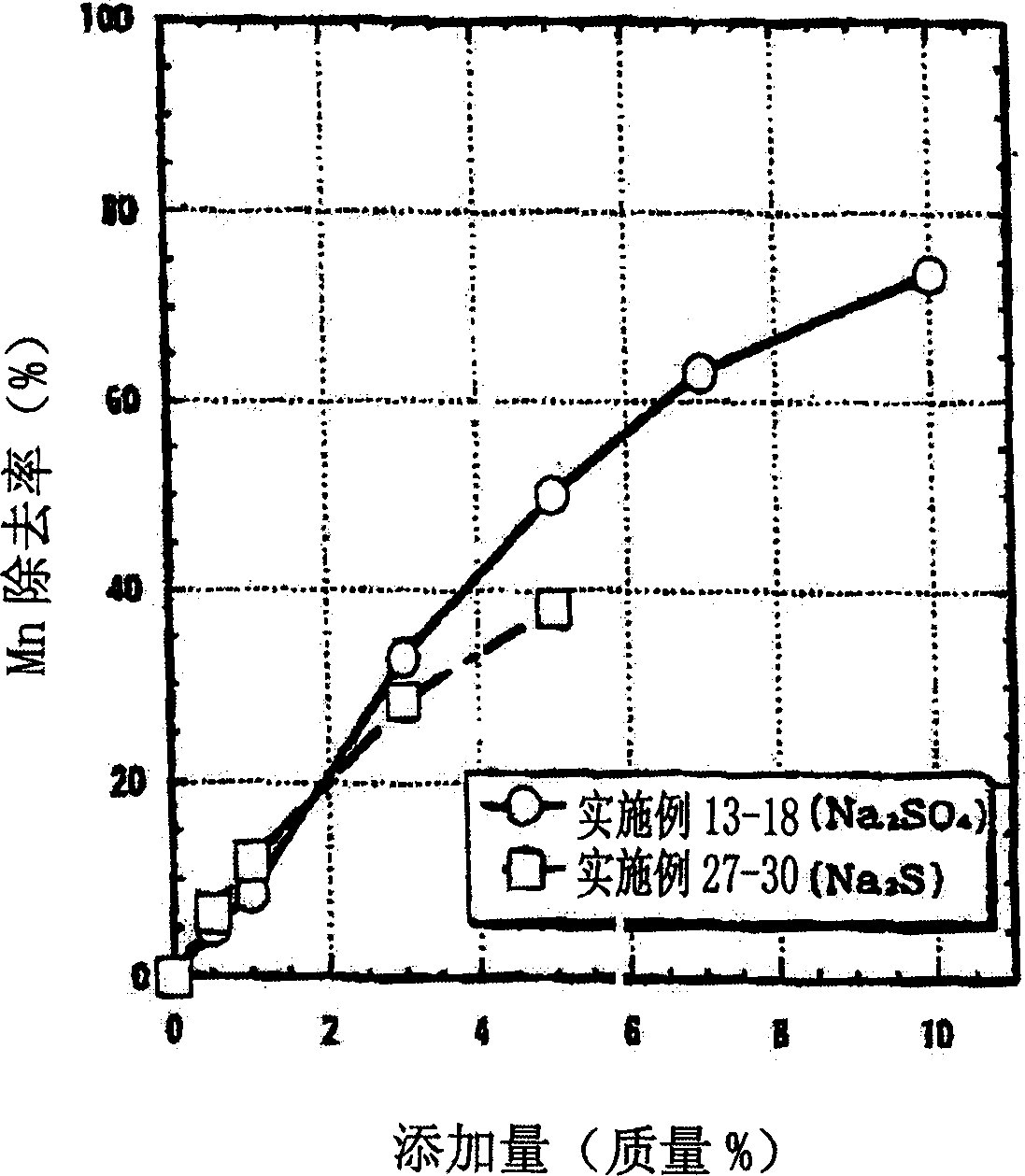
[0092] The Mn removal rate (%) was determined in the same manner as in Examples 1 to 6, except that a master alloy formulated to contain 1.5% by mass of Mn was used. Table 1 shows Mn and other chemical components (% by mass) of the master alloy. Na 2 SO 4 The addition amount is 0.5 mass % (embodiment 13), 1 mass % (embodiment 14), 3 mass % (embodiment 15), 5 mass % (embodiment 16), 7 mass % (embodiment 17), 10 mass % Mass % (Example 18). image 3 shows Na according to Examples 13-18 2 SO 4 The relationship between the amount of addition and the removal rate of Mn.


PUM

PropertyMeasurementUnit
tensile strengthaaaaaaaaaa

Abstract

A method for removing manganese in molten cast iron, characterized in that it comprises adding sodium sulfate while mixing into a molten cast iron as an additive, or adding sodium sulfide while mixing into a molten cast iron as an additive, adding hydrogen sodium sulfide while mixing into a molten cast iron as an additive. The method can be employed in the production of cast iron, and thus allows the production of a cast iron of high ductility which is improved in elongation characteristics without detriment to tensile strength, even when a steel scrap being cheap and having a high Mn content is used as a raw material.

Description

technical field [0001] This invention relates to the removal of manganese in the manufacture of cast iron. Background technique [0002] Among cast irons, nodular cast iron is used in various applications because it has particularly excellent mechanical properties and is relatively inexpensive. Its applications include, for example, auto parts, especially parts suitable for running parts of cars such as lower arms, upper arms, steering knuckle housings, and suspensions. Ductile cast iron is also called high toughness cast iron, which generally refers to cast iron in which graphite crystallizes into spherical shapes in the cast state. [0003] Among the mechanical properties of this ductile iron, the tensile strength is usually in the range of 400-500MPa, but it can be increased to about 800MPa depending on the alloy composition. The elongation decreases with the increase of the strength. Although FDC450 (Japanese Industrial Standards) generally stipulates that the tensile ...

Claims


Application Information

Patent Timeline
Patent Type & Authority Applications(China)
IPC IPC(8): C21C1/10
CPCC21C1/10Y02P10/20
Inventor 铃木克美堀江皓
Owner ASAHI TEC CORP
Learn More