Calculating circuit for calculating sampling phase error
A technology for computing circuits and sampling phases, applied in electrical components, line transmission components, digital transmission systems, etc., can solve problems such as instability and inability to prevent unstable calibration
- Summary
- Abstract
- Description
- Claims
- Application Information
AI Technical Summary
Problems solved by technology
Method used
Image
Examples
Embodiment Construction
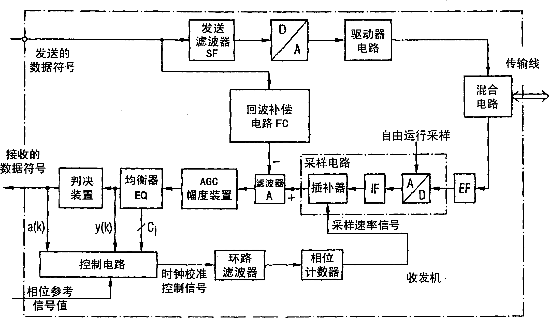
[0120] Picture 9 It represents a sampling phase error detector or calculation circuit 1 for calculating a sampling phase error signal of the present invention that can be applied to the receiver 2.
[0121] Through the line 5, the data source 3 in the transmitter 4 provides the transmission data symbol a to the digital transmission filter 6 for shaping of the transmission pulse. Via line 7, the digital-to-analog converter 8 in the transmitter 4 is connected to the downstream digital transmitting filter 6. The digital-to-analog converter 8 operates with the aid of the symbol clock pulse TTx. The analog converted transmission signal is transmitted from the transmitter 4 to the receiver 2 through the transmission channel 9. The data transmission channel 9 is a time-varying data transmission channel, which is a data transmission channel connected by a line. Noise is additionally superimposed on the received signal.
[0122] Receiver 2 includes the aid of clock pulse T RX Operating a...
PUM
 Abstract
Description
Claims
Application Information
 - Generate Ideas
- Intellectual Property
- Life Sciences
- Materials
- Tech Scout
- Unparalleled Data Quality
- Higher Quality Content
- 60% Fewer Hallucinations
Browse by: Latest US Patents, China's latest patents, Technical Efficacy Thesaurus, Application Domain, Technology Topic, Popular Technical Reports.
© 2025 PatSnap. All rights reserved.Legal|Privacy policy|Modern Slavery Act Transparency Statement|Sitemap|About US| Contact US: help@patsnap.com


