
Nanocomposite for fuel cell bipolar plate

A technology of fuel cells and conductive plates, applied in fuel cell components, nanotechnology for materials and surface science, fuel cells, etc., can solve problems such as amazing prices

Inactive Publication Date: 2003-09-03
HONEYWELL INT INC
View PDF7 Cites 17 Cited by
  • Summary
  • Abstract
  • Description
  • Claims
  • Application Information

AI Technical Summary

Problems solved by technology

But the price of adopting them is astonishing

Method used


Image

  • Nanocomposite for fuel cell bipolar plate
  • Nanocomposite for fuel cell bipolar plate
  • Nanocomposite for fuel cell bipolar plate

Examples


Embodiment Construction

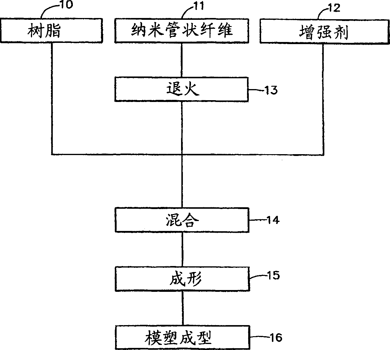
[0047] For the trademark PyrografIII produced by Applied Scienees Inc. TM The carbon nanotube-like fibers were sieved at 20 mesh and annealed at 2000° C. for 12 hours. Combine this fiber with Alcon TM Mix, Aclon TM The addition amount of this fiber is 25, 30, 40 and 45 wt.%. No other enhancers were added. The mixture was pelletized and pressure molded to form a 2 mm thick flow field plate. The above procedure was repeated, but annealed at 3000°C and the resin was a polypropylene copolymer ("PP") from Solvay Polymers under the trade mark Polypropylene TG7904. The added amount of fiber is 30wt% and 40wt%. The flow field plates are also made of graphite powder, and Aclon TM The addition amount of graphite is 70wt.%. The surface specific resistance through the plate was measured by a four-probe technique.

[0048] image 3 is a plot of specific resistance versus carbon loading for the above plates. The results showed that the electrical resistance was reduced by 1 / 2-1 / 3 ...


PUM

PropertyMeasurementUnit
diameteraaaaaaaaaa
diameteraaaaaaaaaa
electrical resistivityaaaaaaaaaa

Abstract

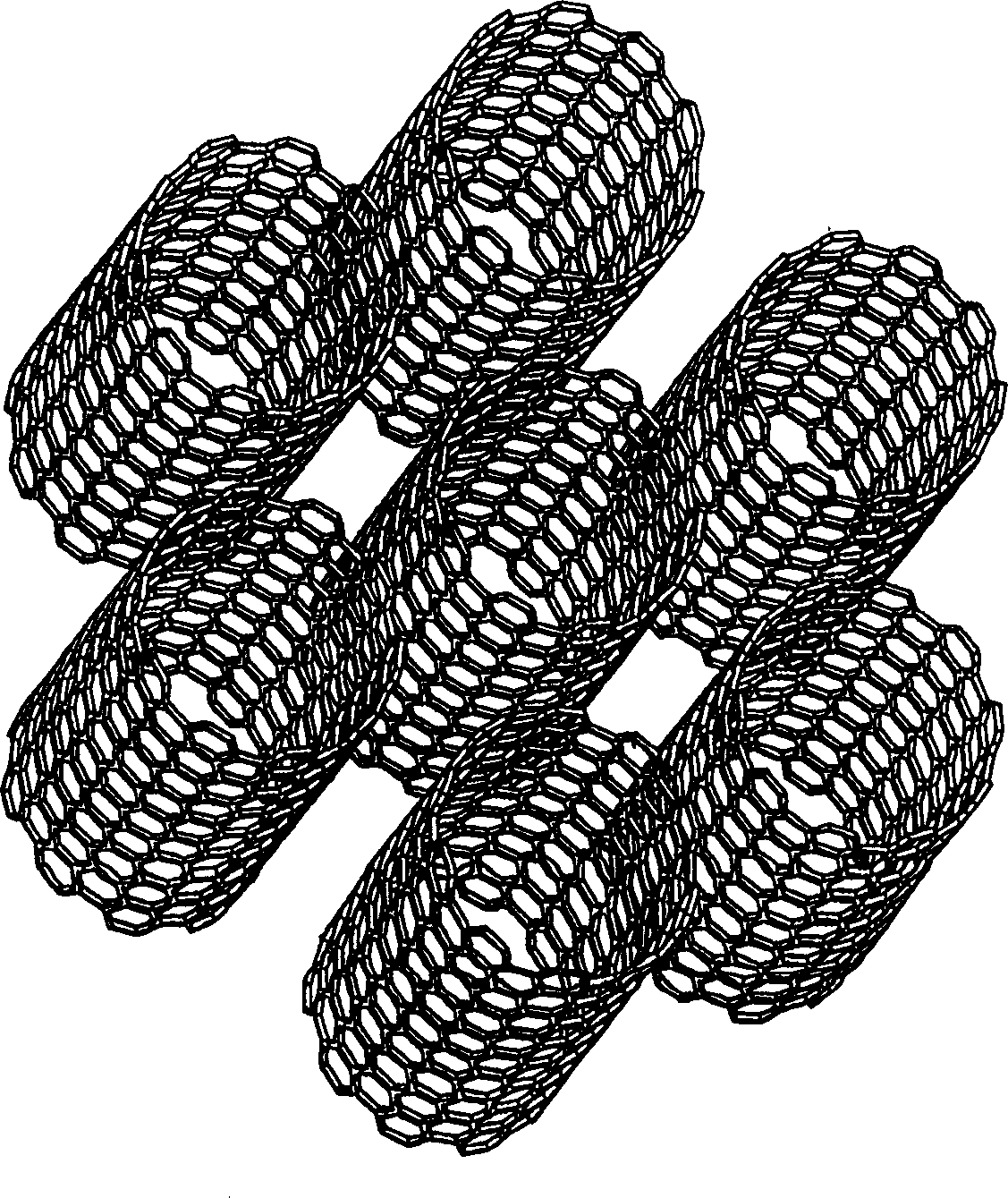
An electrically conductive flow-field plate in a proton exchange membrane fuel cell comprises a composition made of a resin and a plurality of carbon nanotubular fibers having an average diameter is at least about 0.5 nm and up to about 300 nm. The carbon nanotubular fibers are present at not more than about 85 wt. %. The resin can be of a thermoplastic type, a fluorinated type, a thermosetting type and a liquid crystalline type.

Description

technical field [0001] The present invention relates generally to fuel cells, and more particularly to improved bipolar plates that are corrosion resistant, have good electrical conductivity, and are inexpensive to manufacture, and methods for their manufacture. Background technique [0002] A fuel cell is an electrical conversion device that catalyzes an electrochemical reaction between fuel and an oxidant to generate direct current. A fuel cell includes a cathode defining a passage for an oxidant and an anode defining a passage for a fuel. A solid electrolyte is sandwiched between the cathode and the anode and separates the cathode from the anode. Each electrochemical cell typically produces a relatively small voltage. Therefore, to obtain useful higher voltages, individual electrochemical cells are connected in series to form a battery pack. Electrical connection between cells is achieved by electrical interconnection between the cathodes and anodes of adjacent cells. ...

Claims


Application Information

Patent Timeline
Patent Type & Authority Applications(China)
IPC IPC(8): H01M8/02
CPCH01M8/0226H01M8/0221Y10S977/948Y10S977/932H01M8/0213H01M8/0252B82Y30/00Y02E60/50Y10S977/734Y10S977/753B82B3/00B82Y40/00H01M8/02H01B1/24
Inventor Z·伊克巴尔D·纳拉辛哈姆T·雷H·戴J·V·圭赫恩J·马特鲁尼希J·普拉特
Owner HONEYWELL INT INC
Learn More