
Automatic eliminating method for self d.c. component in power metering system

A technology of DC component and power measurement, which is applied in the direction of electric power measurement through current/voltage, electric power measurement through application of digital technology, and measurement of electric variables, etc. It can solve the complexity of phase compensation circuit design and the difficulty of process control, Problems such as complex structure and large chip scale

Inactive Publication Date: 2003-09-03
VIMICRO CORP
View PDF0 Cites 8 Cited by
  • Summary
  • Abstract
  • Description
  • Claims
  • Application Information

AI Technical Summary

Problems solved by technology

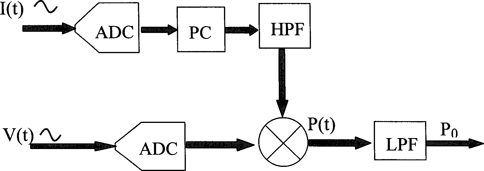
[0014] First of all, because the high-pass filter is implemented after the A / D conversion, a digital filter must be used, and its structure is relatively complicated, which makes the chip scale large.
[0015] Secondly, since one of the signals in the current and voltage channels uses high-pass filtering, the phase drift is caused in this signal. In order to make the power factor of the measured active power truly reflect the phase characteristics between the input signals, it is necessary Phase correction is performed on this signal, but the result of introducing a phase compensation circuit is to increase the complexity of the design and the difficulty of process control

Method used


Image

  • Automatic eliminating method for self d.c. component in power metering system
  • Automatic eliminating method for self d.c. component in power metering system
  • Automatic eliminating method for self d.c. component in power metering system

Examples


Embodiment Construction

[0061] best practice

[0062] The present invention will be described in more detail below with reference to non-limiting examples and drawings.

[0063] When the present invention is actually implemented, a variety of different circuit modes can be adopted, and what is described below is an optimal solution when considering the complexity and cost minimization of system design.

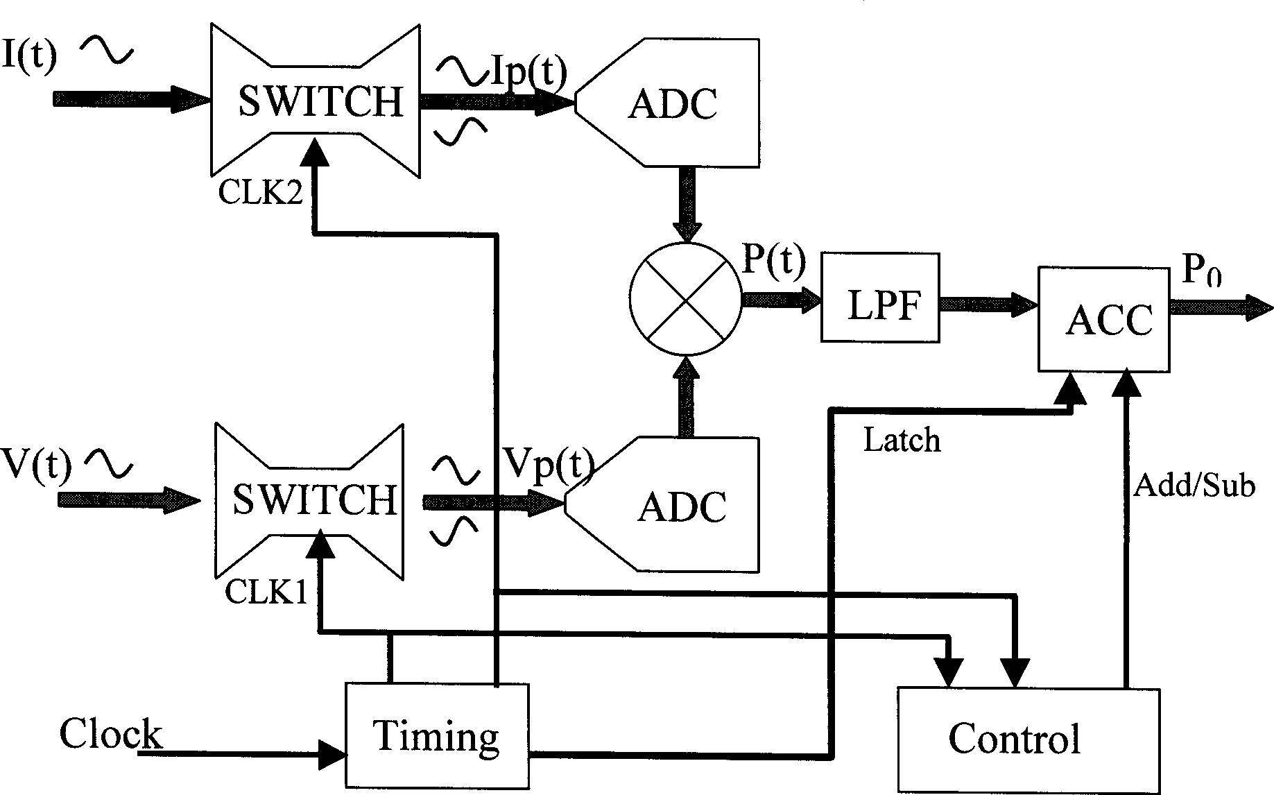
[0064] 1. In the attached image 3 In the above functional block diagram, the external input signals V(t) and I(t) are input by differential pairs, so that the polarity converter SWITCH can conveniently perform polarity conversion.

[0065] 2. The timing of the module can be simple 2 n The frequency division operation is completed, and the required CLK1, CLK2 and Latch signals are generated respectively.

[0066] 3. The design of the polarity converter SWITCH can be realized simply by using a CMOS "choose one" analog switch circuit

[0067] 4. The ADC module is implemented with a 1-bit oversampli...


PUM


Abstract

A technique for automatically eliminating the self DC component of system in power metering features that a very simple and effective circuit structure is used to automatically elimitate the measuring error caused by input misadjustment, and in turn the false power caused by internet DC component (misadjustment). If the input signal has a DC component, it can be used to calculate active power.

Description

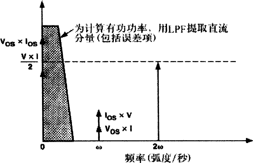
technical field [0001] The invention relates to the field of power metering, and in more detail, relates to a technology for automatically eliminating the direct current component of an all-electronic power metering system. Background technique [0002] With the continuous development of electronic technology, all-electronic power metering technology has entered various fields of science and technology and is playing an irreplaceable role. [0003] However, in all known all-electronic power (energy) metering devices, there is a problem that the DC component (current or voltage imbalance) of the metering system itself will affect the metering results, resulting in false power (energy) ), thereby reducing the measurement accuracy. [0004] According to the definition of apparent power, active power and energy, assuming that the input voltage signal is V(t)=Vcos(ω·t), the input current signal is I(t)=Icos(ω·t), then the apparent The power P(t) is obtained by the following for...

Claims


Application Information

Patent Timeline
Patent Type & Authority Applications(China)
IPC IPC(8): G01R21/06G01R21/133G01R22/00
Inventor 胡健张韬金志俊付永文
Owner VIMICRO CORP
Learn More