Apparatus for making frequency-variable grating using holographical method

A holographic method and grating technology, applied in the field of frequency conversion grating, can solve the problem that the spatial frequency cannot be made very high

Inactive Publication Date: 2003-08-27
SHANGHAI INST OF OPTICS & FINE MECHANICS CHINESE ACAD OF SCI
View PDF0 Cites 2 Cited by
  • Summary
  • Abstract
  • Description
  • Claims
  • Application Information

AI Technical Summary

Problems solved by technology

The advantage is that it is relatively simple, and it does not have strict requirements on the accuracy of the experimental device like the previous method. The disadvantage is that since the incident light is incident from the curved surface of the cylindrical mirror, in order to

Method used


Image

  • Apparatus for making frequency-variable grating using holographical method
  • Apparatus for making frequency-variable grating using holographical method

Examples


Embodiment Construction

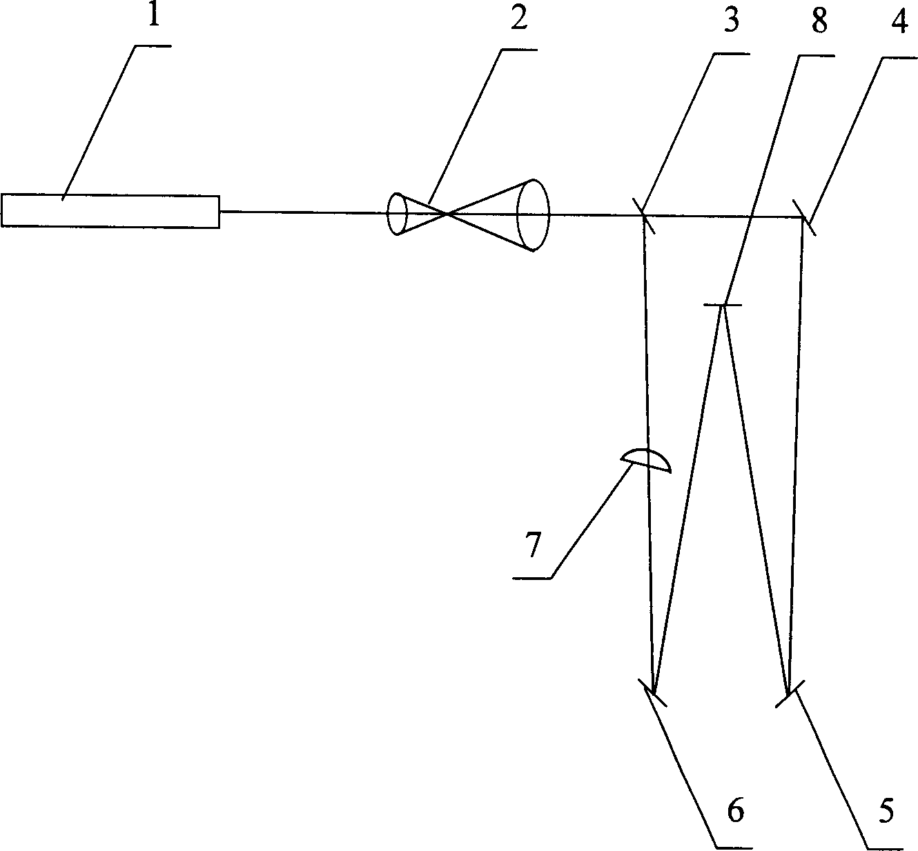
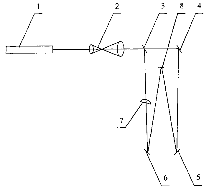
[0037] The holographic method of the present invention makes frequency conversion grating device such as figure 1 As shown, it consists of a laser light source 1, a telescope 2, a beam splitter 3, mirrors 4, 5, 6, a cylindrical mirror 7 and a recording medium 8, and its specific

[0038] The parameters of the embodiment are as follows:

[0039]Laser source 1 is a single-mode He-Ne laser with an output power of 5mW; telescope 2 is a beam expander system with a magnification of 100 times, and its function is to expand the beam with a diameter of 1mm into a beam with a diameter of 100mm; Beamer 3 is a wedge-shaped plate with a reflectivity of 50%, which is used to split the light coming out of the telescope into two, one beam is the reference wave Cb, and the other beam is the object wave Wb.

[0040] Mirrors 4, 5, 6 are total reflection mirrors, and the light beam Wb reflected from beam splitter 3 arrives at mirror 6 through cylindrical mirror 7 and is reflected on recording me...


PUM


Abstract

The device comprises the laser light source, the beam-expanding telescope, the beam splitter, the reflector, the cylindrical mirror and the recording media. The laser beam from the laser source being expanded by the telescope enters the beam splitter to divide the beam into two light beams: the reflected beam and the transmitted beam. The reflector reflects the reflected beam passed through the cylindrical mirror to the recording media as the object wave. The reflector reflects the transmitted light to the holographic recording media as the reference wave. The interference between the object wave and the reference wave forms hologram recorded on the media. The spatial frequency of the variable frequency grating made by the device is changed in linearity.

Description

Technical field: [0001] The invention relates to a frequency-variable grating, in particular to a device for making a frequency-variable (or complex pitch) grating by holography. Background technique: [0002] In recent years, variable frequency gratings have been widely used in defense industry, scientific research, industrial production and other departments, especially in synchrotron radiation soft-X-ray beamlines, which have been widely used. For example, frequency conversion gratings are used in Spring-8 in Japan, synchrotron radiation facilities in Hefei and Beijing in China. Changing the groove spacing of the grating according to a certain rule can reduce aberrations, shorten the space length of the monochromator, improve the efficiency of the monochromator, etc., and can also achieve self-focusing and overcome various problems introduced by the focusing mirror at the output end. Aberrations and more. [0003] The frequency conversion grating is made by using the me...

Claims


Application Information

Patent Timeline
IPC IPC(8): G02B5/18G03H1/22
Inventor 陈建文高鸿奕谢红兰徐至展熊诗圣
Owner SHANGHAI INST OF OPTICS & FINE MECHANICS CHINESE ACAD OF SCI
Why Eureka
Try Eureka