Pattern

A surface pattern and mosaic technology, applied in the field of surface patterns, can solve the problem of converting unpredetermined patterns into diffraction structures, etc.

Inactive Publication Date: 2006-07-19
OVD KINEGRAM AG
View PDF6 Cites 0 Cited by
  • Summary
  • Abstract
  • Description
  • Claims
  • Application Information

AI Technical Summary

Problems solved by technology

Due to inestimable influences in the etching process, it is not possible to precisely convert the predetermined pattern into a diffractive structure

Method used


Image

  • Pattern
  • Pattern
  • Pattern

Examples


Embodiment Construction

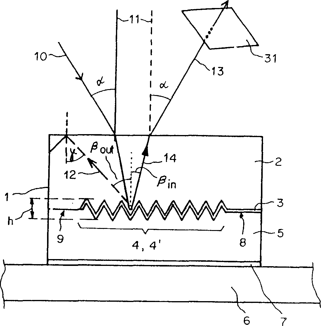
[0023] figure 1 In, reference numeral 1 denotes a laminate, 2 denotes a transparent covering layer made of polymer, 3 denotes a reflective layer, 4 denotes a microscopic concave-convex structure, 5 denotes a protective layer made of polymer, and 6 denotes a substrate. The protective layer 5 away from the reflective layer 3 is either covered by the adhesive layer 7, or the protective layer 5 itself has an adhesive function. Suitable for bonding are cold bonding or hot melt bonding, the choice of bonding depends on how it will be used. Form microscopic concave-convex structure 4 in cover layer 2, and cover with reflective layer 3, reflective layer 3 also covers the surface part 8 and 9 that do not have structure at the same time, wherein, surface part 8 and reflective layer 3 serve as specular reflective surface 8 together, Alternatively, the surface portion 9 is provided without the reflective layer 3 as a transparent window 9 . The protective layer 5 is either visible throug...


PUM


Abstract

A surface pattern (18) is in the form of a visually visible mosaic comprising a number of surface portions (8; 9; 15; 16; 17) and is embedded in a laminate (1) comprising at least a transparent cover layer (2) and a protective layer (5). The surface portions (8; 9; 15; 16; 17) are transparent, scatter or reflect incident light (10) or diffract the incident light (10) at microscopic relief structures (4). The surface portions (8; 9; 15; 16; 17) are at least partially covered with a reflection layer (3). At least one of the surface portions occupied by a microscopic relief structure (4), an area (16), is a ZOM-structure (4') with a predeterminedly slowly varying profile height h and a spatial frequency f, wherein the product of a predetermined limit wavelength lambdaG of the visible spectrum and the spatial frequency f is greater than or equal to one.

Description

technical field [0001] The present invention relates to a surface pattern with a visually visible mosaic comprising a plurality of diffractive surface portions with microscopic relief embedded within a stack. [0002] Such a surface pattern has a microscopically fine concave-convex structure and is suitable as an anti-counterfeiting element to enhance the anti-counterfeiting ability of valuable notes or securities and bonds, passes, means of payment and other valuable contracts against forgery. Background technique [0003] WO 87 / 07034 describes a surface pattern with 3 surface portions having light-efficient diffractive structures. The surface pattern has three surface portions containing optically effective diffractive structures. These structures have a spatial frequency f and can diffract visible light at wavelength λ to different diffraction angles α. The profile height h of the grooves of the three structures is constant in each surface portion, but in each surface p...

Claims


Application Information

Patent Timeline
Patent Type & Authority Patents(China)
IPC IPC(8): G02B5/18G06K19/16B42D15/10G07D7/12
CPCB42D25/391B42D25/328B42D2035/22G02B5/1842B42D2035/42G06K19/16
Inventor 韦恩·R·汤普金雷内·斯陶布
Owner OVD KINEGRAM AG
Why Eureka
Try Eureka